MITSUBISHI MICROCOMPUTERS
M37270MF-XXXSP
M37270EF-XXXSP, M37270EFSP
SINGLE-CHIP 8-BIT CMOS MICROCOMPUTER with CLOSED CAPTION DECODER
and ON-SCREEN DISPLAY CONTROLLER
FUNCTIONAL DESCRIPTION
Central Processing Unit (CPU)
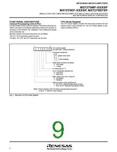
CPU Mode Register
The CPU mode register contains the stack page selection bit and
The M37270MF-XXXSP uses the standard 740 family instruction set.
Refer to the table of 740 family addressing modes and machine in-
structions or the SERIES 740 <Software> User’s Manual for details
on the instruction set.
internal system clock selection bit. The CPU mode register is allo-
cated at address 00FB16.
Machine-resident 740 family instructions are as follows:
The FST, SLW instruction cannot be used.
The MUL, DIV, WIT and STP instruction can be used.
7
0
0
CPU mode register
(CPUM (CM) : address 00FB16)
1
1
0
Processor mode bits
b1 b0
0 0 : Single-chip mode
0 1 :
1 0 :
1 1 :
Not available
Stack page selection bit (Note)
0 : Zero page
1 : 1 page
Fix these bits to “1.”
XCOUT drivability selection bit
0 : Low drive
1 : High drive
Main colock (XIN–XOUT) stop bit
0 : Oscillating
1 : Stopped
Internal system clock selection bit
0 : XIN–XOUT selected (high-speed mode)
1 : XCIN–XCOUT selected (low-speed mode)
Note: Please beware of this bit when programming because it
is set to “1” after the reset release.
Fig. 1. Structure of CPU mode register
8

 RENESAS [ RENESAS TECHNOLOGY CORP ]