ICL7611, ICL7612
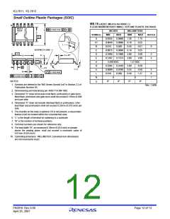
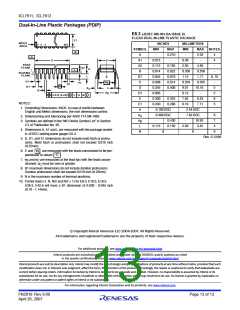
Dual-In-Line Plastic Packages (PDIP)
E8.3 (JEDEC MS-001-BA ISSUE D)
N
8 LEAD DUAL-IN-LINE PLASTIC PACKAGE
E1
INDEX
AREA
INCHES
MILLIMETERS
1 2
3
N/2
SYMBOL
MIN
MAX
0.210
-
MIN
-
MAX
5.33
-
NOTES
-B-
-C-
A
A1
A2
B
-
4
-A-
D
E
0.015
0.115
0.014
0.045
0.008
0.355
0.005
0.300
0.240
0.39
2.93
0.356
1.15
0.204
9.01
0.13
7.62
6.10
4
BASE
PLANE
0.195
0.022
0.070
0.014
0.400
-
4.95
0.558
1.77
0.355
10.16
-
-
A2
A
-
SEATING
PLANE
L
C
L
B1
C
8, 10
D1
B1
eA
-
A
A
1
D1
e
D
5
eC
C
B
eB
D1
E
5
0.010 (0.25) M
C
B S
0.325
0.280
8.25
7.11
6
NOTES:
E1
e
5
1. Controlling Dimensions: INCH. In case of conflict between
0.100 BSC
0.300 BSC
2.54 BSC
7.62 BSC
-
English and Metric dimensions, the inch dimensions control.
e
e
6
A
B
2. Dimensioning and tolerancing per ANSI Y14.5M-1982.
-
0.430
0.150
-
10.92
3.81
7
3. Symbols are defined in the “MO Series Symbol List” in Section
2.2 of Publication No. 95.
L
0.115
2.93
4
9
4. Dimensions A, A1 and L are measured with the package seated
N
8
8
in JEDEC seating plane gauge GS-3.
Rev. 0 12/93
5. D, D1, and E1 dimensions do not include mold flash or protru-
sions. Mold flash or protrusions shall not exceed 0.010 inch
(0.25mm).
e
6. E and
pendicular to datum
7. e and e are measured at the lead tips with the leads uncon-
are measured with the leads constrained to be per-
A
-C-
.
B
C
strained. e must be zero or greater.
C
8. B1 maximum dimensions do not include dambar protrusions.
Dambar protrusions shall not exceed 0.010 inch (0.25mm).
9. N is the maximum number of terminal positions.
10. Corner leads (1, N, N/2 and N/2 + 1) for E8.3, E16.3, E18.3,
E28.3, E42.6 will have a B1 dimension of 0.030 - 0.045 inch
(0.76 - 1.14mm).
© Copyright Intersil Americas LLC 2004-2007. All Rights Reserved.
All trademarks and registered trademarks are the property of their respective owners.
For additional products, see www.intersil.com/en/products.html
Intersil products are manufactured, assembled and tested utilizing ISO9001 quality systems as noted
in the quality certifications found at www.intersil.com/en/support/qualandreliability.html
Intersil products are sold by description only. Intersil may modify the circuit design and/or specifications of products at any time without notice, provided that such
modification does not, in Intersil's sole judgment, affect the form, fit or function of the product. Accordingly, the reader is cautioned to verify that datasheets are
current before placing orders. Information furnished by Intersil is believed to be accurate and reliable. However, no responsibility is assumed by Intersil or its
subsidiaries for its use; nor for any infringements of patents or other rights of third parties which may result from its use. No license is granted by implication or
otherwise under any patent or patent rights of Intersil or its subsidiaries.
For information regarding Intersil Corporation and its products, see www.intersil.com
FN2919 Rev 9.00
April 26, 2007
Page 13 of 13

 RENESAS [ RENESAS TECHNOLOGY CORP ]