15.2.2
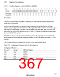
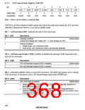
A/D Control/Status Register (ADCSR)
Bit
7
ADF
0
6
ADIE
0
5
ADST
0
4
SCAN
0
3
2
1
0
CKS
0
CH2
0
CH1
0
CH0
0
Initial value
Read/Write
R/(W)*
R/W
R/W
R/W
R/W
R/W
R/W
R/W
Note: * Only 0 can be written, to clear the flag.
ADCSR is an 8-bit readable/writable register that selects the mode and controls the A/D converter.
ADCSR is initialized to H'00 by a reset and in standby mode.
Bit 7—A/D End Flag (ADF): Indicates the end of A/D conversion.
Bit 7: ADF
Description
0
Clearing condition:
(Initial value)
Cleared by reading ADF while ADF = 1, then writing 0 in ADF
1
Setting conditions:
•
•
Single mode: A/D conversion ends
Scan mode: A/D conversion ends in all selected channels
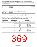
Bit 6—A/D Interrupt Enable (ADIE): Enables or disables the interrupt (ADI) requested at the
end of A/D conversion.
Bit 6: ADIE
Description
0
1
A/D end interrupt request (ADI) is disabled
A/D end interrupt request (ADI) is enabled
(Initial value)
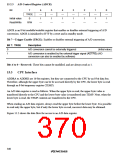
Bit 5—A/D Start (ADST): Starts or stops A/D conversion. The ADST bit remains set to 1 during
A/D conversion. It can also be set to 1 by external trigger input at the ADTRG pin.
Bit 5: ADST
Description
0
1
A/D conversion is stopped
(Initial value)
•
Single mode: A/D conversion starts; ADST is automatically cleared to 0
when conversion ends
•
Scan mode: A/D conversion starts and continues, cycling among the
selected channels, until ADST is cleared to 0 by software, by a reset, or by
a transition to standby mode
338

 RENESAS [ RENESAS TECHNOLOGY CORP ]