12.3.2
Asynchronous Mode
In asynchronous mode, each transmitted or received character is individually synchronized by
framing it with a start bit and stop bit.
Full duplex data transfer is possible because the SCI has independent transmit and receive
sections. Double buffering in both sections enables the SCI to be programmed for continuous data
transfer.
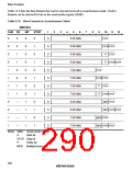
Figure 12.2 shows the general format of one character sent or received in asynchronous mode. The
communication channel is normally held in the mark state (high). Character transmission or
reception starts with a transition to the space state (low).
The first bit transmitted or received is the start bit (low). It is followed by the data bits, in which
the least significant bit (LSB) comes first. The data bits are followed by the parity or
multiprocessor bit, if present, then the stop bit or bits (high) confirming the end of the frame.
In receiving, the SCI synchronizes on the falling edge of the start bit, and samples each bit at the
center of the bit (at the 8th cycle of the internal serial clock, which runs at 16 times the bit rate).
Idle state
Parity or
(mark)
Start bit
1 bit
D0
D1
Dn
multipro-
Stop bit
cessor bit
7 or 8 bits
0 or 1 bit 1 or 2 bits
One unit of data (one character or frame)
Figure 12.2 Data Format in Asynchronous Mode
(Example of 8-Bit Data with Parity Bit and Two Stop Bits)
259

 RENESAS [ RENESAS TECHNOLOGY CORP ]