12.2.9
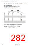
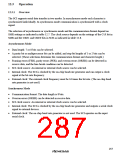
Serial/Timer Control Register (STCR)
Bit
7
6
5
4
3
STAC
0
2
1
ICKS1
0
0
ICKS0
0
IICS
0
IICD
0
IICX
0
IICE
0
MPE
0
Initial value
Read/Write
R/W
R/W
R/W
R/W
R/W
R/W
R/W
R/W
STCR is an 8-bit readable/writable register that controls the SCI operating mode and selects the
TCNT clock source in the 8-bit timers. STCR is initialized to H'00 by a reset.
Bits 7 to 4—I2C Control (IICS, IICD, IICX, IICE): These bits control operation of the I2C bus
interface. For details, refer to section 13, I2C Bus Interface.
Bit 3—Slave Input Switch (STAC): Controls the input pin of the host interface. For details, refer
to section 14, Host Interface.
Bit 2—Multiprocessor Enable (MPE): Enables or disables the multiprocessor communication
function on channels SCI0 and SCI1.
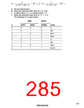
Bit 2: MPE
Description
0
The multiprocessor communication function is disabled, regardless of the
setting of the MP bit in SMR.
(Initial value)
1
The multiprocessor communication function is enabled. The multiprocessor
format can be selected by setting the MP bit in SMR to 1.
Bits 1 and 0—Internal Clock Source Select 1 and 0 (ICKS1, ICKS0): These bits select the
clock input to the timer counters (TCNT) in the 8-bit timers. For details, see section 9, 8-Bit
Timers.
256

 RENESAS [ RENESAS TECHNOLOGY CORP ]