Section 15 14-Bit PWM
15.4
Operation
When using the 14-bit PWM, set the registers in this sequence:
1. Set the PWM bit in the port mode register 1 (PMR1) to set the P11/PWM pin to function as a
PWM output pin.
2. Set the PWCR0 bit in PWCR to select a conversion period of either.
3. Set the output waveform data in PWDRU and PWDRL. Be sure to write byte data first to
PWDRL and then to PWDRU. When the data is written in PWDRU, the contents of these
registers are latched in the PWM waveform generator, and the PWM waveform generation
data is updated in synchronization with internal signals.
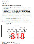
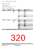
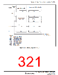
One conversion period consists of 64 pulses, as shown in figure 15.2. The total high-level width
during this period (TH) corresponds to the data in PWDRU and PWDRL. This relation can be
expressed as follows:
TH = (data value in PWDRU and PWDRL + 64) × tφ/2
where tφ is the period of PWM clock input: 2/φ (bit PWCR0 = 0) or 4/φ (bit PWCR0 = 1).
If the data value in PWDRU and PWDRL is from H'FFC0 to H'FFFF, the PWM output stays high.
When the data value is H'C000, TH is calculated as follows:
TH = 64 × tφ/2 = 32 tφ
Conversion period
t f1
t f2
t f63
t f64
t H1
t H2
t H3
t H63
t H64
...
T H = t H1 + t H2 + t H3 + + t H64
...
t f1 = t f2 = t f3 = = t f64
Figure 15.2 Waveform Output by 14-Bit PWM
Rev. 3.00 Sep. 10, 2007 Page 284 of 528
REJ09B0216-0300

 RENESAS [ RENESAS TECHNOLOGY CORP ]