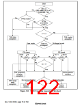
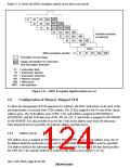
Figure 3.13 shows the MMU exception signals in the data access mode.
IF
ID EX MA WB
MA
WB
IF
ID EX
IF ID EX MA WB
ID EX MA WB
ID EX MA WB
ID EX MA WB
NOP
Handler transition
processing
NOP
ID EX MA WB
MMU exception handler
IF
: Exception source stage
: Stage cancellation for instruction
that has begun execution
IF = Instruction fetch
ID = Instruction decode
EX = Instruction execution
MA = Memory access
WB = Write back
NOP = No operation
Figure 3.13 MMU Exception Signals in Data Access
3.6
Configuration of Memory-Mapped TLB
To allow the management of TLB operations by software, the MOV instruction can be used, in the
privileged mode, to read and write TLB contents. The TLB is mapped to the P4 area of the virtual
address space. The TLB address array (VPN, V bit, and ASID) is mapped to H'F2000000 to
H'F2FFFFFF, and the TLB data array (PPN, PR, SZ, CD, S, and H bits) is mapped to H'F3000000
to H'F3FFFFFF. It is also possible to access the V bits in the address array from the data array.
Only longword access is possible, for both the address and data arrays.
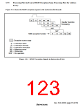
3.6.1
Address Array
The address array is mapped to H'F2000000 to H'F2FFFFFF. To access the address array, the 32-
bit address field (for read/write access) and 32-bit data field (for write access) must be specified.
The address field has the information that selects the entry to be accessed; the data field specifies
the VPN, the V bit, and the ASID to be written to the address array (figure 3.14 (1)).
Rev. 5.00, 09/03, page 80 of 760

 RENESAS [ RENESAS TECHNOLOGY CORP ]