INTERRUPTS
6.5 Interrupt priority level detection circuit
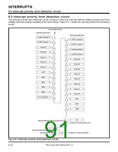
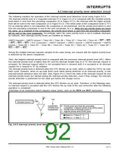
The following explains the operation of the interrupt priority level detection circuit using Figure 6.5.2.
The interrupt priority level of a requested interrupt (Y in Figure 6.5.2) is compared with the resultant priority
level which is sent from the preceding comparator (X in Figure 6.5.2); the interrupt with the higher priority
level will be sent to the next comparator (Z in Figure 6.5.2). (The initial value of the comparison level is “0.”)
For an interrupt which is not requested, the comparison is not performed, and the priority level which is sent
from the preceding comparator is sent to the next comparator as it is. When the two priority levels are found
the same, as a resultant of the comparison, the priority level which is sent from the preceding comparator
will be sent to the next comparator. Accordingly, when the same priority level is set to multiple interrupts
by software, their interrupt priority levels are handled as follows:
UART2 transmit > UART2 receive > Timer A9 > Timer A8 > Timer A7 > Timer A6 > Timer A5 > INT
> INT > INT > INT > A-D conversion > UART1 transmit > UART1 receive > UART0 transmit > UART0
receive > Timer B2 > Timer B1 > Timer B0 > Timer A4 > Timer A3 > Timer A2 > Timer A1 > Timer A0 >
INT > INT > INT
7
> INT
6
5
4
3
2
1
0
Among the multiple interrupt requests sampled at the same timing, one request with the highest priority level
is detected by the above comparison.
Then, this highest interrupt priority level is compared with the processor interrupt priority level (IPL). When
this interrupt priority level is higher than IPL and the interrupt disable flag (I) is “0,” the interrupt request is
accepted. An interrupt request which is not accepted here is retained until it is accepted or its interrupt
request bit is cleared to “0” by software.
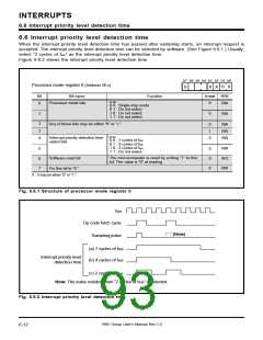
The interrupt priority level is detected when the CPU fetches an op code, which is called the CPU’s op-code
fetch cycle. However, when an op-code fetch cycle starts during detection of an interrupt priority, a new
interrupt priority detection does not start. (See Figure 6.6.2.) Since the state of the interrupt request bit and
interrupt priority levels are latched during the interrupt priority detection, even if they change, the interrupt
priority detection is performed for the state just before the change occurs.
The interrupt priority level is detected when the CPU fetches an op code. Therefore, in the following case,
no interrupt request is accepted until the CPU fetches the op code of the next instruction after the following
operation is completed:
•Execution of an instruction which requires many cycles, such as the MVN and MVP instructions
X
Time
Y
Interrupt source Y
Comparator
(Priority level
comparison)
X : Priority level sent from the preceding
comparator (Highest priority level at this point)
Y : Priority level of interrupt source Y
Z : Highest priority level at this point
Z
➀When X ≥ Y then Z = X
➀When X < Y then Z = Y
Fig. 6.5.2 Interrupt priority level detection model
7905 Group User’s Manual Rev.1.0
6-11

 RENESAS [ RENESAS TECHNOLOGY CORP ]