STOP AND WAIT MODES
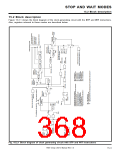
15.2 Block description
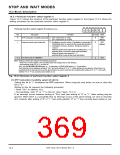
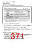
15.2.2 Particular function select register 1
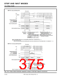
Figure 15.2.4 shows the structure of the particular function select register 1.
b7 b6 b5 b4 b3 b2 b1 b0
Particular function select register 1 (Address 6316
)
0
0
Bit
0
Bit name
Function
At reset R/W
0 : Normal operation.
1 : During execution of STP instruction
STP-instruction-execution
status bit
(Note 1) RW
(Note 2)
0 : Normal operation.
1 : During execution of WIT instruction
WIT-instruction-execution
status bit
1
(Note 1) RW
(Note 2)
Fix this bit to “0.”
0
0
2
3
RW
0 : In the wait mode, system clock fsys is active.
1 : In the wait mode, system clock fsys is inactive.
System clock stop select bit
at WIT
RW
(Note 3)
0
0
0
RW
—
4
5
6
Fix this bit to “0.”
The value is “0” at reading.
Timer B2 clock source select bit 0 : External signal input to the TB2IN pin is counted.
(Valid in event counter mode.)
RW
1 : fX32 is counted.
(Note 4)
—
The value is “0” at reading.
0
7
Notes 1: At power-on reset, this bit becomes “0.” At hardware reset or software reset, this bit retains the value just before reset.
2: Even when “1” is written, the bit status will not change.
3: Setting this bit to “1” must be performed just before execution of the WIT instruction. Also, after the wait state is termi-
nated, this bit must be cleared to “0” immediately.
4: When using timer B2 in the pulse period/pulse width measurement mode, be sure to clear this bit to “0.”
Fig. 15.2.4 Structure of particular function select register 1
(1) STP-instruction-execution status bit (bit 0)
When the microcomputer enters the stop mode, this bit becomes “1,” indicating that the STP instruction
has been executed.
This bit becomes “0” at power-on reset. At hardware reset and software reset, this bit retains the value
immediately before reset. Therefore, this bit is used for the following verification:
• Which of the power-on reset and hardware reset has been used to reset the system?
• Has the hardware reset been used for the stop mode termination?
This bit is cleared to “0” by writing “0” to this bit. Although, even when “1” is written to this bit, this
bit does not change.
At the stop mode termination, be sure to clear this bit to “0” by software.
(2) WIT-instruction-execution status bit (bit 1)
When the microcomputer enters the wait mode, this bit becomes “1,” indicating that the WIT instruction
has been executed.
This bit becomes “0” at power-on reset. At hardware reset and software reset, this bit retains the value
immediately before reset. Therefore, this bit is used for the following verification:
• Which of the power-on reset and hardware reset has been used to reset the system?
• Has the hardware reset been used for the wait mode termination?
This bit is cleared to “0” by writing “0” to this bit. Although, even when “1” is written to this bit, this
bit does not change.
At the wait mode termination, be sure to clear this bit to “0” by software.
7905 Group User’s Manual Rev.1.0
15-6

 RENESAS [ RENESAS TECHNOLOGY CORP ]