A-D CONVERTER
12.10 Repeat sweep mode 0
12.10 Repeat sweep mode 0
In the repeat sweep mode, the A-D conversions for input voltages from multiple selected analog input pins
are performed repeatedly. The A-D conversion is performed in ascending sequence from pin AN0 to pin AN .
7
In this mode, no A-D conversion interrupt request occurs. Additionally, the A-D conversion start bit (bit 6 at
address 1E16) remains set to “1” until it is cleared to “0” by software, and the A-D converter repeats its
operation while the A-D conversion start bit = “1.”
This mode can be used with analog input pins AN (j = 0 to 7).
j
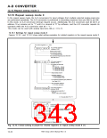
12.10.1 Settings for repeat sweep mode 0
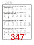
Figures 12.10.1 and 12.10.2 show initial setting examples for related registers in the repeat sweep mode 0.
A-D control registers 0, 1, and 2
b7
b0
A-D control register 0
(Address 1E16
✕
0
0
1 1 ✕ ✕
)
Repeat sweep mode 0
A-D conversion start bit
0 : A-D conversion halts.
A-D conversion frequency (φAD) select bit 0
See Table 12.2.1.
b7
b0
A-D control register 1
0
0
0
(Address 1F16
)
A-D sweep pin select bits
b1b0
0 0 : AN
0 1 : AN
1 0 : AN
1 1 : AN
0
0
0
0
, AN
1
(2 pins)
(4 pins)
(6 pins)
(8 pins)
to AN
to AN
to AN
3
5
7
Repeat sweep mode 0
Resolution select bit
0 : 8-bit resolution mode
1 : 10-bit resolution mode
A-D conversion frequency (φAD) select bit 1
See Table 12.2.1.
VREF connection select bit
0 : Pin VREF connected
b7
b0
A-D control register 2
✕
✕
✕
0
0
0
0
0
(Address DB16
)
Analog input pin select bits 1
b3 b2 b1 b0
0
X X X : AN0 to AN7 selected
✕ : It may be either “0” or “1.”
Selection of comparator function
b7
b0
Comparator function select register 0
(Address DC16
)
AN
AN
AN
AN
AN
AN
AN
AN
0
0 : Comparator function is not selected.
1 : Comparator function is selected.
1
2
3
4
5
6
7
Continued on Figure 12.10.2.
Fig. 12.10.1 Initial setting example for related registers in repeat sweep mode 0 (1)
7905 Group User’s Manual Rev.1.0
12-32

 RENESAS [ RENESAS TECHNOLOGY CORP ]