A-D CONVERTER
12.9 Single sweep mode
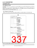
12.9 Single sweep mode
In the single sweep mode, the operation for the input voltages from multiple selected analog input pins are
performed, one at a time. The operation is performed in ascending sequence from pin AN0 to pin AN7. An
A-D conversion interrupt request occurs when the operations for all selected analog input pins are completed.
This mode can be used with analog input pins AN (j = 0 to 7).
j
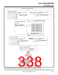
12.9.1 Settings for single sweep mode
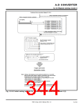
Figures 12.9.1 and 12.9.2 show initial setting examples for related registers in the single sweep mode.
When using an interrupt, it is necessary to set the related registers to enable an interrupt. Refer to
“CHAPTER 6. INTERRUPTS” for more details.
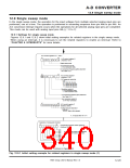
A-D control registers 0, 1, and 2
b7
b0
A-D control register 0
(Address 1E16)
0
0
1
0
✕ ✕
✕
Single sweep mode
A-D conversion start bit
0 : A-D conversion halts.
A-D conversion frequency (φAD) select bit 0
See Table 12.2.1.
b7
b0
A-D control register 1
(Address 1F16)
0
0
0
A-D sweep pin select bits
b1b0
0 0 : AN
0 1 : AN
1 0 : AN
1 1 : AN
0
0
0
0
, AN1 (2 pins)
to AN
to AN
to AN
3
5
7
(4 pins)
(6 pins)
(8 pins)
Resolution select bit
0 : 8-bit resolution mode
1 : 10-bit resolution mode
A-D conversion frequency (φAD) select bit 1
See Table 12.2.1.
VREF connection select bit
0 : Pin VREF connected
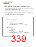
b7
b0
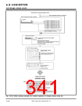
A-D control register 2
(Address DB16)
0
0
0
0 0
✕ ✕
✕
Analog input pin select bits 1
b3 b2 b1 b0
0
X X X : AN0 to AN7 selected
✕ : It may be either “0” or “1.”
Selection of comparator function
b7
b0
Comparator function select register 0
(Address DC16
)
AN
AN
AN
AN
AN
AN
AN
AN
0
1
2
3
4
5
6
7
0 : Comparator function is not selected
1 : Comparator function is selected.
Continued on Figure 12.9.2.
Fig. 12.9.1 Initial setting example for related registers in single sweep mode (1)
7905 Group User’s Manual Rev.1.0
12-29

 RENESAS [ RENESAS TECHNOLOGY CORP ]