A-D CONVERTER
12.7 One-shot mode
12.7 One-shot mode
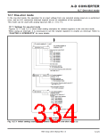
In the one-shot mode, the operation for an input voltage from one selected analog input pin is performed
once, and an A-D conversion interrupt request occurs at completion of the operation.
This mode can be used with analog input pin AN (i = 0 to 11).
i
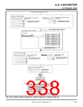
12.7.1 Settings for one-shot mode
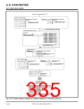
Figures 12.7.1 and 12.7.2 show initial setting examples for related registers in the one-shot mode.
When using an interrupt, it is necessary to set the related registers to enable an interrupt. Refer to
“CHAPTER 6. INTERRUPTS” for more details.
A-D control registers 0, 1, and 2
A-D control register 0
(Address 1E16
b7
b0
)
0
0 0 0
Analog input pin select bits 0
b2b1 b0
0 0 0 : AN
0 0 1 : AN
0 1 0 : AN
0 1 1 : AN
1 0 0 : AN
1 0 1 : AN
1 1 0 : AN
1 1 1 : AN
0
1
2
3
4
5
6
7
selected
selected
selected
selected
selected
selected
selected
selected
One-shot mode
A-D conversion start bit
0 : A-D conversion halts.
A-D conversion frequency (φAD) select bit 0
See Table 12.2.1.
b7
b0
A-D control register 1
0 0
0
✕ ✕
(Address 1F16
)
Resolution select bit
0 : 8-bit resolution mod
1 : 10-bit resolution mode
A-D conversion frequency (φAD) select bit 1
See Table 12.2.1.
V
REF connection select bit
0 : Pin VREF connected
b7
b0
A-D control register 2
(Address DB16
0
0
0 0
)
Analog input pin select bits 1
b3 b2 b1 b0
0
X X X : AN
0
8
9
to AN
selected
selected
7
selected
1 0 0 0 : AN
1 0 0 1 : AN
1 0 1 0 : AN10 selected
1 0 1 1 : AN11 selected
1 1 0 0 : Do not select.
1 1 1 1 : Do not select.
✕ : It may be either “0” or “1.”
Continued on Figure 12.7.2.
Fig. 12.7.1 Initial setting example for related registers in one-shot mode (1)
7905 Group User’s Manual Rev.1.0
12-23

 RENESAS [ RENESAS TECHNOLOGY CORP ]