SERIAL I/O
11.4 Clock asynchronous serial I/O (UART) mode
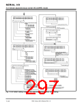
11.4.4 Transmit operation
When the receive conditions described in section “11.4.3 Method of transmission” have been satisfied,
a transfer clock is generated, and the following operations are automatically performed after 1 cycle of the
transfer clock or less has passed.
•The UARTi transmit buffer register’s contents are transferred to the UARTi transmit register.
•The transmit buffer empty flag is set to “1.”
•The transmit register empty flag is cleared to “0.”
•A UARTi transmit interrupt request occurs, and the interrupt request bit is set to “1.”
The transmit operations are described below:
✕ Data in the UARTi transmit register is transmitted from the TxD pin.
i
✕ This data is transmitted bit by bit sequentially in order of ST→DATA (LSB)→•••→DATA (MSB)→PAR
→SP according to the transfer data format.
✕ The transmit register empty flag is set to “1” at the center of the stop bit (or the second stop bit if 2 stop
bits selected). This indicates completion of transmission. Additionally, whether the transmit conditions
for the next data are satisfied or not is examined.
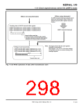
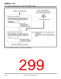
When the transmit conditions for the next data are satisfied in step ✕, the start bit is generated following
the stop bit, and the next data is transmitted. When performing transmission continuously, be sure to set
the next transmit data in the UARTi transmit buffer register during transmission (i.e. when the transmit
register empty flag = “0”). When the transmit conditions for the next data are not satisfied, the TxD
outputs “H” level and the transfer clock stops.
i
pin
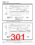
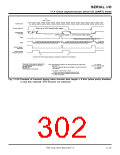
Figures 11.4.7 and 11.4.8 show examples of transmit timing when the transfer data length = 8 bits, and
Figure 11.4.9 shows an example of transmit timing when the transfer data length = 9 bits.
7905 Group User’s Manual Rev.1.0
11-45

 RENESAS [ RENESAS TECHNOLOGY CORP ]