RTL8169S-32/RTL8169S-64
Datasheet
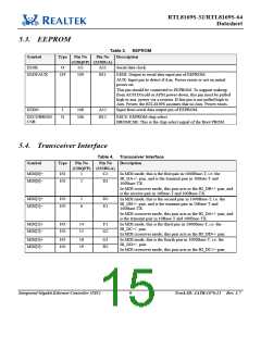
5.3. EEPROM
Table 3. EEPROM
Symbol
Type
Pin No
Pin No
Description
(128QFP) (233BGA)
EESK
O
111
109
A11
B11
Serial data clock.
EEDI/AUX
O/I
EEDI: Output to serial data input pin of EEPROM.
AUX: Input pin to detect if Aux. Power exists or not on initial
power-on.
This pin should be connected to EEPROM. To support wakeup
from ACPI D3cold or APM power-down, this pin must be pulled
high to aux. power via a resistor. If this pin is not pulled high to
Aux. Power, the RTL8169S assumes that no Aux. Power exists.
EEDO
I
108
106
A12
B12
Input from serial data output pin of EEPROM.
EECS/BROM
CSB
O
EECS: EEPROM chip select
BROMCSB: This is the chip select signal of the Boot PROM.
5.4. Transceiver Interface
Table 4. Transceiver Interface
Symbol
Type
Pin No
Pin No
Description
(128QFP) (233BGA)
MDI[0]+
I/O
I/O
1
2
C2
D1
In MDI mode, this is the first pair in 1000Base-T, i.e. the
BI_DA+/- pair, and is the transmit pair in 10Base-T and
100Base-TX.
MDI[0]−
In MDI crossover mode, this pair acts as the BI_DB+/- pair, and
is the receive pair in 10Base-T and 100Base-TX.
MDI[1]+
I/O
I/O
5
6
D2
E1
In MDI mode, this is the second pair in 1000Base-T, i.e. the
BI_DB+/- pair, and is the transmit pair in 10Base-T and
100Base-TX.
MDI[1]−
In MDI crossover mode, this pair acts as the BI_DA+/- pair, and
is the transmit pair in 10Base-T and 100Base-TX.
MDI[2]+
I/O
I/O
14
15
F1
In MDI mode, this is the third pair in 1000Base-T, i.e. the
BI_DC+/- pair.
In MDI crossover mode, this pair acts as the BI_DD+/- pair.
MDI[2]−
G2
MDI[3]+
I/O
I/O
18
19
G1
H2
In MDI mode, this is the fourth pair in 1000Base-T, i.e. the
BI_DD+/- pair.
In MDI crossover mode, this pair acts as the BI_DC+/- pair.
MDI[3]−
Integrated Gigabit Ethernet Controller (NIC)
9
Track ID: JATR-1076-21 Rev. 1.7

 REALTEK [ Realtek Semiconductor Corp. ]