VRS51L1050
C
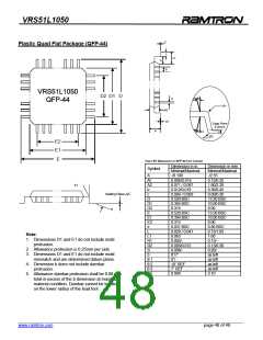
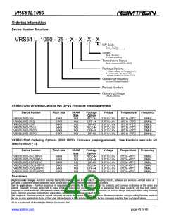
Plastic Quad Flat Package (QFP-44)
L
L1
S
S
VRS51L1050
D2 D1 D
2
b
QFP-44
R1
A2
A1
Gage Plane
0.25mm
A
3
R2
E2
E1
E
TABLE 55: DIMENSIONS OF QFP-44 CHIP CARRIER
Dimension in in.
Symbol
Dimension in mm
Minimal/Maximal
-/2.55
Minimal/Maximal
A
-/0.100
Al
A2
b
c
D
D1
D2
E
E1
E2
e
0.006/0.014
0.071 / 0.087
0.012/0.018
0.004 / 0.009
0.520 BSC
0.394 BSC
0.315
0.520 BSC
0.394 BSC
0.315
0.031 BSC
0.029 / 0.041
0.063
0.005/-
0.005/0.012
0.008/-
0.15/0.35
1.80/2.20
0.30/0.45
0.09/0.20
13.20 BSC
10.00 BSC
8.00
13.20 BSC
10.00 BSC
8.00
0.80 BSC
0.73/1.03
1.60
0.13/-
0.13/0.30
0.20/-
e1
C
Seating Plane
e
L
Note:
L1
R1
R2
S
1. Dimensions D1 and E1 do not include mold
protrusion.
2. Allowance protrusion is 0.25mm per side.
3. Dimensions D1 and E1 do not include mold
mismatch and are determined datum plane.
4. Dimension b does not include dambar
protrusion.
5. Allowance dambar protrusion shall be 0.08 mm
total in excess of the b dimension at maximum
material condition. Dambar cannot be located
on the lower radius of the lead foot.
0
0˚/7˚
0˚/ -
10˚ REF
7˚ REF
0.004
as left
as left
as left
as left
θ 1
θ 2
θ 3
∆C
0.10
______________________________________________________________________________________________
www.ramtron.com page 48 of 49

 RAMTRON [ RAMTRON INTERNATIONAL CORPORATION ]