©Quantum Research Group Ltd.
8 Index
A
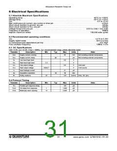
adc, 8
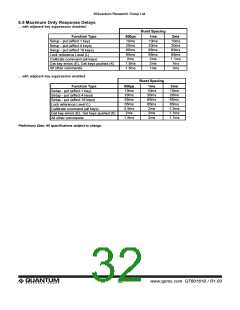
adjacent key suppression, 6, 7, 12, 24, 28, 32
alert output
led, 10, 11
I
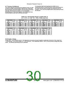
intra-burst pulse spacing, 9, 23
K
key design, 4
key numbering convention, 18
key reporting, 20
application assistance, 4
L
led
alert output, 10, 11
lock reference levels, 6, 14, 23, 24
B
block diagram, 5
boundary limits, 19, 23, 29
burst length, 4, 7, 8, 9, 17, 21, 28, 30
burst spacing, 8, 9, 14, 22, 28, 30, 32
burst timing, 15, 30
M
master mode, 12, 13
master-slave mode, 4, 12, 13
miso, 12, 13
mosi, 9, 12, 13
C
calibration
recalibration, 5, 6, 7, 9, 10, 17, 19, 21, 23, 24, 29
N
circuit model, 7
cs, 5, 8, 9
negative detect integrator, 22
negative detect threshold, 21
negative drift compensation, 22
negative hysteresis, 5
negative recalibration delay, 6, 23
negative reference error band, 23
negative threshold, 5, 7, 8, 21, 22, 23
noise, 11, 12
D
delta signals, 19, 27
detection integrator, 5, 6, 8, 18
direction commands, 17
drdy’, 12
noise filter, 22. see also emi
drift compensation, 5, 6, 11, 17, 21, 22, 23
dwell, 7, 9
O
oscillator, 7, 9, 10, 12, 14, 25
oscilloscope sync, 11, 26
E
echo, 12, 13, 15, 21, 24
eeprom checksum, 18, 24
electrostatic shield, 11
emi, 11, 23
P
pcb layout, 4, 11
rfi, 8, 9, 21
positive detect threshold, 21
positive recalibration delay, 6, 7, 23
positive reference error band, 23
positive threshold, 5, 6, 7, 21, 23
power supply, 11
error code, 4, 11, 16, 17, 19, 20, 21, 23
error guardbanding, 23
esd protection, 8, 9, 11
F
field flow, 4, 8
function summary table, 27
pulse spacing, 9, 23
put command, 17
Q
qmbtn, 4, 10, 11
G
get command, 17
ground plane, 11
R
recalibrate keys (command), 24
recalibration
calibration, 5, 6, 7, 9, 10, 17, 19, 21, 23, 24, 29
reset, 7, 9, 10, 11, 17, 25, 26
resonator, 7, 9. see also oscillator
return last command, 25
H
hysteresis, 5, 21, 22
lQ
34
www.qprox.com QT60161B / R1.03

 QUANTUM [ QUANTUM RESEARCH GROUP ]