©Quantum Research Group Ltd.
^G 0
X
07 - BURST
SPACING
Bytes / Cmd Byte 2 Range
^I 0
X
09 - POSITIVE
D
Bytes / Cmd Byte 2 Range
RIFT
C
OMPENSATION
R
ATE
Scope
16
16
Returns
0x07
0x00..0x02
Scope
1, 4, 16
1
Returns
0x09
0x01..0x64
Put
Get
2
1
0x00..0x02
n/a
Put
Get
2
1
0x01..0x64
n/a
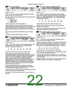
Section 3.8, p. 9
Section 2.4, p. 5
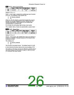
Ctrl-G. In Put mode, sets the spacing between successive
acquire bursts for the entire matrix.
Ctrl-I. Same as ^H above in all respects, except operates
only when the signal is positive with respect to the reference
level, i.e. in an abnormal direction. It is usually desirable to
set this rate much faster than for ^H, i.e. to a lower number.
Valid decimal values are:
The second byte indicates the spacing to be set according to
the following table:
0: 500µs (0.5ms)
1: 1000µs (1ms)
2: 2000µs (2ms)
1
15
2
20
3
25
4
33
6
45
8
60
10 12
75 100
Values higher than 2 will be truncated to 2.
Values other than the above will be rounded down.
Values of 4 to 10 (0.4 to 1.0 secs/count) are considered
Longer delay times equate to slower matrix scanning. At
lower delay times (faster rep rates) there can be conflicts with suitable for most systems.
long burst lengths and long conversion times which will
Positive drift compensation continues to operate even if the
signal has exceeded the positive threshold.
prevent proper operation; see also Section 3.6, and Section
5.7.
Burst spacing also affects recalibration time; see Section
2.10.
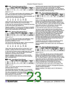
^J 0x0A - NEGATIVE
D
ETECT
I
NTEGRATOR
L
Bytes / Cmd Byte 2 Range
IMIT
Scope
1, 4, 16
1
Returns
0x0A
0x00..0xFF
Put
Get
2
1
0x00..0xFF
n/a
The scope for this function is always 'all keys'.
^H 0
X
08 - NEGATIVE
D
RIFT
C
Bytes / Cmd Byte 2 Range
OMPENSATION
R
ATE
5
Section 2.6, p. 6
Scope
1, 4, 16
1
Returns
0x08
0x01..0x64
Ctrl-J. In Put mode, sets the detection integration limit for
one or more keys according to scope.
Put
Get
2
1
0x01..0x64
n/a
The unit of measure is a burst, i.e. a setting of 5 means that a
detection must be sensed 5 bursts in sequence. A burst for a
Ctrl-H. In Put mode, sets the rate of drift compensation used key occurs once every complete matrix scan. The second
Section 2.4, p. 5
during periods of non-detection, in the negative signal
direction. Valid decimal values are:
byte must be one of the following values (shown in decimal):
0
1
2
3
5
20 32 45 60 90 123 175 255
7
10 15
1
15
2
20
3
25
4
33
6
45
8
60
10 12
75 100
Values other than the above will be rounded down.
Values other than the above will be rounded down.
In Get mode, the command will return a single byte according
to the current scope rules (Section 5.2).
These numbers correspond to the amount of drift
compensation applied, in 100ms/count of reference change,
for signals which are negative with respect to the reference
level, i.e. in the same direction as legitimate detections.
Higher numbers equate to slower drift compensation.
Overcompensation (too fast) can result in the suppression of
legitimate detections. Under-compensation can result in
inadequate compensation for rapid environmental changes.
Values of 15 to 45 (1.5 to 4.5 secs/count) are considered
normal under most conditions.
This setup can be used as a noise filter, or as a mechanism
to intentionally slow down key reaction time in order to require
a long user touch.
Special condition: If the value for ^J is set to zero the key is
disabled, but the burst for the key is still generated.
Drift compensation does not occur while the signal has
passed below the negative threshold level or subsequently
remained below the negative hysteresis level.
In Get mode, the command will return a single byte according
to the current scope rules (Section 5.2).
The scope in Put mode can be one key, a row or column, or
all keys.
lQ
22
www.qprox.com QT60161B / R1.03

 QUANTUM [ QUANTUM RESEARCH GROUP ]