©Quantum Research Group Ltd.
output response is found on the YS lines (pins 23..26), and
eeprom. As intentional writes in Put mode should only occur
during manufacture, it is normally safe to assume that
eeprom changes during normal run mode are errors.
these are also active high. The bit pattern found on the YS
lines indicates any keys that are touched; like a real matrix,
the device can set multiple bits on the YS lines.
The host can also periodically test the checksum of the
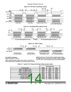
The host should scan to individual lines XS0..XS3. XS0 maps eeprom as a backup mechanism to the bit 4 error flag.
to matrix drive line X0 (pin 13). The response on YS0 maps to
The uppercase ‘L’ command, Lock Reference Levels, also
matrix line Y0. Thus, the scan port logic exactly mimics the
writes data to eeprom, and this data also has the potential to
wiring and scanning of the matrix keys.
become corrupted. This data is also backed up in Flash so
The parallel scan port operates on a continuous basis, but is that it can be recovered, and an error in this data will also set
slower to react when either serial port is in operation. If either bit 4 and also alter the checksum. Also, the ‘L’ command only
serial port is operational, the scan port updates with every
acquisition burst, i.e. 16 times during a complete scan of the
matrix.
operates if the device is in Put mode as a further protection.
Flash memory has a limit of 1,000 write cycles, so
copy-to-Flash should not be used often.
For a full-time higher speed scan port response, it should be
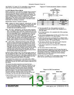
enabled as the sole interface via the option jumper settings
shown in Figure 4-1. The port itself is found on pins 19
through 26 (Figure 3-2). In this dedicated mode, the scan port
outputs within 100µs of receiving a scan input from the host.
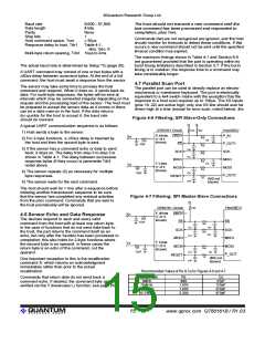
Error scan: The host can extract error information from the
scan port by setting all XS lines to logical '1' simultaneously.
The part then returns a high level on any YS lines
corresponding to Y matrix lines having key errors. Thus a
single YS bit, if high, could indicate errors on any or all of 4
keys. Errors are reported for the following conditions:
a. Key(s) are currently recalibrating
b. Key(s) tried to calibrate 5 times and failed each time
c. Key(s) signal references are under- or over- limit
It is not possible to determine the cause of the error or
specific key(s) in error via the parallel scan port.
4.8 Eeprom Corruption
The device stores its Setup data in an internal eeprom which
can be readily altered via Put mode commands. Sometimes
noise on Vdd, the SPI lines or Reset pin can cause eeprom
corruption which can be difficult or inconvenient to correct.
The device should always be left in Get mode to prevent
spurious commands from corrupting the eeprom. The Get
command should ideally be repeated every second or so to
ensure that if noise on the SPI lines causes a false Put mode
command that it does not last long. Preferably, the ‘l’
command (lowercase ‘L’) should be used to verify that the Put
command has succeeded.
Flash backup: The part backs up the entire eeprom array
into onboard Flash rom after one or more Setup write
commands have been issued and the part is then reset.
During normal operation the part constantly compares the
Flash area with the eeprom array to ensure the two sections
match. If an eeprom error is detected, the device sets an
error flag (bit 4) in the general device status byte (Command
‘7’, page 19) which can be read by the host device. The LED
output also becomes active. If the bit 4 error flag is set, the
host should immediately induce a device reset.
Bit 4 is also set if an intentional write has been made to
eeprom, but not yet copied into Flash via the reset process. It
is perfectly acceptable to continue altering any number of
Setup parameters prior to doing the reset, ignoring this bit.
During power up or after a reset, the device compares the
Flash area with eeprom, and if there is a discrepancy the
eeprom is refreshed from Flash, unless an intentional write
was detected in which case the Flash is updated from the
lQ
16
www.qprox.com QT60161B / R1.03

 QUANTUM [ QUANTUM RESEARCH GROUP ]