©Quantum Research Group Ltd.
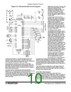
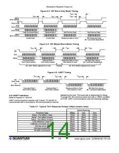
Figure 4-3 SPI Slave-Only Mode Timing
T
dr3
T
cm
T
T
dr1
dr2
DRDY
{from sensor}
SS
{from host}
SCK
{from host}
MOSI
{from host}
7 6 5 4 3 2 1 0
7 6 5 4 3 2 1 0
Optional Byte 2
Host Command Byte 1
Null Dummy Data
7 6 5 4 3 2 1 0
Null Dummy Data
7 6 5 4 3 2 1 0
MISO
{from sensor}
7 6 5 4 3 2 1 0
Invalid Data
7 6 5 4 3 2 1 0
Invalid Data
Response Data or Echo
Nth Response Data
{N = command dependent}
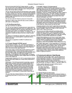
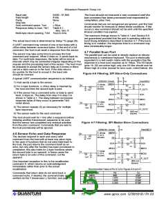
Figure 4-4 SPI Master/Slave Mode Timing
T
T
T
cm
dr1
dr3
SS
SCK
MOSI
7 6 5 4 3 2 1 0
7 6 5 4 3 2 1 0
7 6 5 4 3 2 1 0
7 6 5 4 3 2 1 0
Command Byte 1
from Host to sensor
Optional Byte 2
from host to sensor
Response Byte or Echo
from sensor to host
Nth Byte from sensor
{N = command dependent}
SS, SCK, MOSI originate from Host
Floating
SS, SCK, MOSI originate from sensor
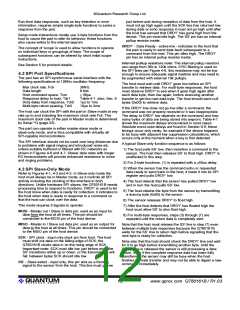
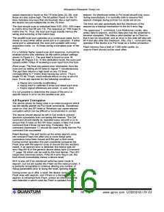
Figure 4-5 UART Timing
T
cm
T
T
dr1
dr3
RX
{from host}
S 0 1 2 3 4 5 6 7
S 0 1 2 3 4 5 6 7
TX
{from sensor}
S 0 1 2 3 4 5 6 7
S 0 1 2 3 4 5 6 7
Command Byte 1
from host to sensor
Optional Byte 2
from host to sensor
Response Byte or Echo
from sensor to host
Nth Byte from sensor
{N = command dependent}
initiated by the host. The baud rate is determined by Setup
^Q (page 25); the maximum baud rate with a 12MHz oscillator
is 57.6K. UART communications uses the following settings:
4.5 UART Interface
Refer to Figures 4-1 and 4-5.
UART communications requires only 2 wires, TX and RX to
communicate with a host device. All communications must be
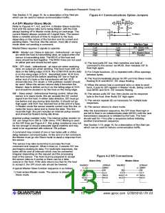
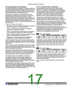
Table 4-1 Typical Tdr1 Response Delays (100µs sample ramp)
Burst Spacing
Function Type
Setup - Put (affect 1 key)
Setup - Put (affect 8 keys)
Setup - Put (affect 16 keys)
Lock reference Level (L)
Calibrate command (all keys)
Get key errors (E)
500µs
10ms
20ms
65ms
65ms
500µs
450µs
350µs
350µs
1ms
10ms
20ms
65ms
65ms
500µs
450µs
350µs
350µs
2ms
10ms
20ms
65ms
65ms
500µs
450µs
350µs
350µs
Get keys pushed (K)
All other commands
lQ
14
www.qprox.com QT60161B / R1.03

 QUANTUM [ QUANTUM RESEARCH GROUP ]