2.8 Fast Detect Mode
2.10 Unused Keys
In many applications, it is desirable to sense touch at high
speed. Examples include scrolling ‘slider’ strips or ‘Off’
buttons. It is possible to place the device into a ‘Fast Detect’
mode that usually requires under 15ms to respond. This is
accomplished internally by setting the Detect Integrator to
only two counts, i.e. only two successive detections are
required to detect touch.
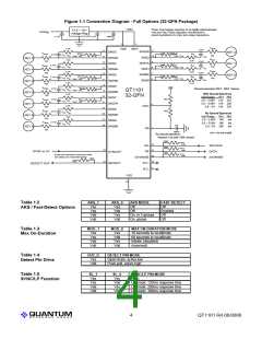
Unused keys should be disabled by removing the
corresponding Cs, Rs, and Rsns components and
connecting SNS pins as shown in the ‘Unused’ column of
Table 1.1. Unused keys are ignored and do not factor into
the AKS function (Section 2.6).
2.11 Serial 1W Interface
In LP mode, ‘Fast’ detection will not speed up the initial
delay (which could be up to 360ms typical depending on the
option setting). However, once a key is detected the device
is forced back into normal speed mode. It will remain in this
faster mode until another LP pulse is received.
The 1W serial interface is an RS-232 based auto baud rate
serial asynchronous interface that requires only one wire
between the host MCU and the QT1101. The serial data are
extremely short and simple to interpret.
Auto baud rate detection takes place by having the host
device send a specific character to the QT1101, which
allows the QT1101 to set its baud rate to match that of the
host.
When used in a ‘slider’ application, it is normally desirable to
run the keys without AKS.
In both normal and ‘Fast’ modes, the time required to
process a key release is the same: it takes six sequential
confirmations of non-detection to turn a key off.
One feature of this method is that the baud rate can be any
rate between 8,000 and 38,400 bits per second. Neither the
QT1101 nor the host device has to be accurate in their
transmission rates, i.e. crystal control is not required.
Fast Detect mode can be enabled as shown in Tables 1.2
and 1.6.
Depending on the timing of a 1W host transmission, the
QT1101 device may need to abort an acquisition burst, and
rerun it after the transmission is complete and a reply has
been sent. As a consequence, each host request can
potentially result in a small, unnoticeable increase in
detection delay.
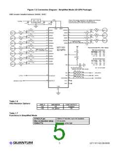
2.9 Simplified Mode
A simplified operating mode which does not require the
majority of option resistors is available. This mode is set by
connecting a resistor labeled SMR between pins SNS6K and
SNS7. (see Figure 1.2).
1W Connection: The 1W pin should be pulled high with a
resistor. When not in use it floats high, hence this causes no
increase in supply current.
In this mode there is only one option available - AKS enable
or disable. When AKS is disabled, Fast Detect mode is
enabled; when AKS is enabled, Fast Detect mode is off.
During transmission from the host, the host may drive the
1W line with either an open-drain or a push-pull driver.
However, if the host uses push-pull driving, it must release
the 1W line as soon as it is done with its stop bit so that
there is no drive conflict when the QT1101 sends its reply.
AKS in this mode is global only (i.e. operates across all
functioning keys).
The other option features are fixed as follows:
DETECT Pin: Push-pull, active high
SYNC/LP Function: LP mode, ~200ms response time
Max On-Duration: 60 seconds
If open-drain transmission is used by the host, the value of
the pull-up resistor should be optimized for the desired baud
rate: faster rates require a lower value of resistor to prevent
rise-time problems. A typical value for 19,200 baud might be
100K✡. An oscilloscope should be used to confirm that the
resistor is not causing excessive timing skew that might
cause bit errors.
See also Tables 1.6 and 1.7.
The QT1101 uses push-pull drive to transmit
data out on the 1W line back to the host. When
the stop bit level is established, 1W is floated;
for this reason, a pull-up resistor should always
be used on the 1W pin to prevent the signal from
drifting to an undefined state. A 100K✡ pull-up
resistor on 1W is recommended, unless the host
uses open-drain drive to the QT1101, in which
case a lower value may be required (see prior
paragraph).
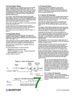
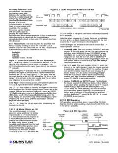
Figure 2.1 Basic 1W Sequence
driven reply
from QT1101
(2 bytes)*
request
from host
(1 byte)
key state
change
1W
/CHANGE floating
floating
floating
floating
2.11.1 Basic 1W Operation
1 ~ 3 bit periods
*See Figure 2.3
The basic sequence of 1W serial operation is
shown in Figure 2.1. The 1W line is bi-directional
and must be pulled high with a resistor to
prevent a floating, undefined state (see previous
section).
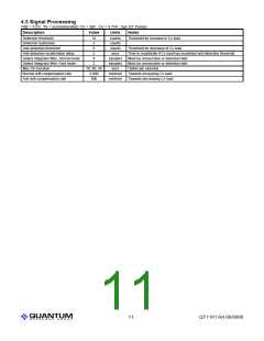
Figure 2.2 1W UART Host Pattern
1W
(from host)
Serial bits
S 0 1 2 3 4 5 6 7 S
Lq
7
QT1101 R4.06/0806

 QUANTUM [ QUANTUM RESEARCH GROUP ]