TOP252-262
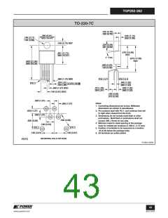
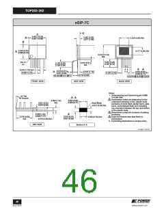
eSIP-7C
C
2
0.403 (10.24)
0.397 (10.08)
0.081 (2.06)
0.077 (1.96)
A
0.224 (5.69) Ref.
B
0.325 (8.25)
0.320 (8.13)
0.177 (4.50) Ref.
2
0.519 (13.18)
Ref.
0.207 (5.26)
0.187 (4.75)
Pin #1
I.D.
0.016 (0.41)
0.140 (3.56)
0.120 (3.05)
Ref.
3
4
0.070 (1.78) Ref.
0.050 (1.27)
0.016 (0.41)
0.011 (0.28)
0.020 M 0.51 M C
A
A
3
0.033 (0.84)
0.028 (0.71)
0.010 M 0.25 M C A B
6×
0.047 (1.19)
6×
0.100 (2.54)
0.118 (3.00)
FRONT VIEW
SIDE VIEW
BACK VIEW
Notes:
1. Dimensioning and tolerancing per ASME
Y14.5M-1994.
10° Ref.
3
4
All Around
2. Dimensions noted are determined at the
outermost extremes of the plastic body
exclusive of mold flash, tie bar burrs, gate
burrs, and interlead flash, but including
any mismatch between the top and bottom
of the plastic body.
0.033 (0.84)
0.028 (0.71)
0.060 (1.52)
Ref.
0.021 (0.53)
0.019 (0.48)
Base Metal
0.012 (0.30) Ref.
3. Dimensions noted are inclusive of plating
thickness.
4. Does not include inter-lead flash or
protrusions.
0.048 (1.22)
0.046 (1.17)
0.019 (0.48) Ref.
3
0.016 (0.41)
0.011 (0.28)
0.378 (9.60)
Ref.
0.030 (0.76) Ref.
5. Controlling dimensions in inches (mm).
END VIEW
Section A–A
PI-4917-123107
46
版本D 08/08
www.powerint.com

 POWERINT [ Power Integrations ]