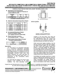
TISPL758LF3D
INTEGRATED SYMMETRICAL AND ASYMMETRICAL BIDIRECTIONAL OVERVOLTAGE
PROTECTORS FOR LUCENT TECHNOLOGIES L7581/2/3 LINE CARD ACCESS SWITCHES
JANUARY 1998 - REVISED OCTOBER 1998
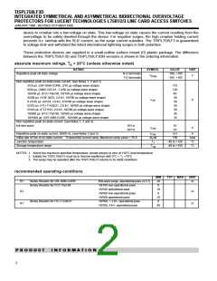
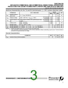
electrical characteristics for the T-G and R-G terminal pairs, T = 25°C (unless otherwise noted)
J
VALUE
PARAMETER
TEST CONDITIONS
VD = ±VDRM, (See Note 4)
dv/dt = ±250 V/ms, RSOURCE = 300 W
Impulse breakover volt- Rated impulse conditions with operational pass series
UNIT
µA
V
MIN
TYP
MAX
Repetitive peak off-
state current
IDRM
±10
R-G terminals -220
T-G terminals -130
R-G terminals -240
T-G terminals -140
+100
+130
+130
+140
+140
V(BO) Breakover voltage
V(BO)
IH
V
age
resistor
di/dt = -30 mA/ms
Holding current
mA
di/dt = +30 mA/ms
-150
ID
Off-state current
0 < VD < ±50 V, TJ = 85°C
±10
36
µA
pF
pF
CTG
CRG
Off-state capacitance
Off-state capacitance
f = 100 kHz, Vd = 1 V rms VTG = -5 V, (See Note 5)
f = 100 kHz, Vd = 1 V rms VTG = -50 V, (See Note 5)
18
10
20
NOTES: 4. Positive and negative values of VDRM are not equal. See ratings table
5. These capacitance measurements employ a three terminal capacitance bridge incorporating a guard circuit. The third terminal is
connected to the guard terminal of the bridge.
thermal characteristics
MIN
TYP
MAX
PARAMETER
UNIT
RqJA
Junction to free air thermal resistance
160
°C/W
P R O D U C T
I N F O R M A T I O N
3

 POINN [ POWER INNOVATIONS LTD ]