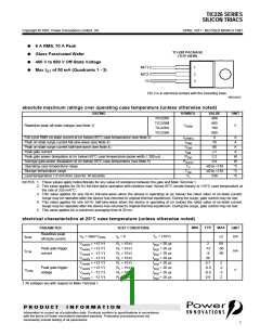
TIC226 SERIES
SILICON TRIACS
APRIL 1971 - REVISED MARCH 1997
electrical characteristics at 25°C case temperature (unless otherwise noted) (continued)
MIN
TYP
MAX
PARAMETER
TEST CONDITIONS
UNIT
VTM
IH
Peak on-state voltage ITM = ±12 A
IG = 50 mA
(see Note 6)
±1.6
5
±2.1
30
V
Vsupply = +12 V†
IG = 0
Init’ ITM = 100 mA
Init’ ITM = -100 mA
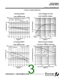
Holding current
Latching current
mA
mA
Vsupply = -12 V†
IG = 0
-9
-30
50
Vsupply = +12 V†
IL
(see Note 7)
Vsupply = -12 V†
-50
Critical rate of rise of
off-state voltage
dv/dt
dv/dt(c)
VDRM = Rated VDRM IG = 0
TC = 110°C
TC = 85°C
±100
V/µs
V/µs
Critical rise of commu-
tation voltage
VDRM = Rated VDRM ITRM = ±12 A
±5
† All voltages are with respect to Main Terminal 1.
NOTES: 6. This parameter must be measured using pulse techniques, tp = £ 1 ms, duty cycle £ 2 %. Voltage-sensing contacts separate from
the current carrying contacts are located within 3.2 mm from the device body.
7. The triacs are triggered by a 15-V (open-circuit amplitude) pulse supplied by a generator with the following characteristics:
RG = 100 W, tp(g) = 20 ms, tr = £ 15 ns, f = 1 kHz.
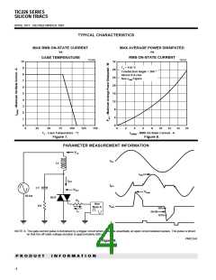
thermal characteristics
PARAMETER
Junction to case thermal resistance
MIN
TYP
MAX
1.8
UNIT
°C/W
°C/W
RqJC
RqJA
Junction to free air thermal resistance
62.5
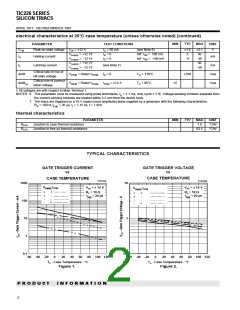
TYPICAL CHARACTERISTICS
GATE TRIGGER CURRENT
vs
GATE TRIGGER VOLTAGE
vs
CASE TEMPERATURE
CASE TEMPERATURE
TC01AA
TC01AB
1000
100
10
10
Vsupply IGTM
VAA = ± 12 V
VAA = ± 12 V
Vsupply IGTM
RL = 10 W
tp(g) = 20 µs
RL = 10 W
tp(g) = 20 µs
+
+
-
+
-
-
+
+
-
+
-
-
-
+
-
+
1
1
0·1
0·1
-60 -40 -20
0
20
40
60
80 100 120
-60 -40 -20
0
20
40
60
80 100 120
TC - Case Temperature - °C
TC - Case Temperature - °C
Figure 1.
Figure 2.
P R O D U C T
I N F O R M A T I O N
2

 POINN [ POWER INNOVATIONS LTD ]