PMC-Sierra, Inc.
PRELIMINARY
PM5381 S/UNI-2488
DATASHEET
PMC-2000489
ISSUE 1
SATURN USER NETWORK INTERFACE FOR 2488 MBIT/S
Notes on Pin Description:
1. All S/UNI-2488 inputs and bidirectionals present minimum capacitive loading and operate at
CMOS/TTL logic levels except: the REFCLK+/-, RXD+/-, TXD+/-, APSI+/-[4:1], APSO+/-[4:1]
pins which operate at pseudo-ECL (PECL) logic levels.
2. The S/UNI-2488 digital outputs and bidirectionals which have 2 mA drive capability are: TBD
The S/UNI-2488 digital outputs and bidirectionals which have 4 mA drive capability are: TBD
The S/UNI-2488 digital outputs and bidirectionals which have 6 mA drive capability are: TBD
3. The S/UNI-2488 digital outputs are 3.3V tolerant.
4. Inputs ALE, RSTB, TMS, TDI and TRSTB have internal pull-up resistors.
5. The single ended pseudo-ECL inputs and outputs should be terminated in a passive network
and interface at PECL levels as described in the Operations section.
6. It is mandatory that every digital ground pin (VSS) be connected to the printed circuit board
ground plane to ensure reliable device operation.
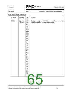
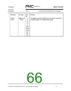
7. It is mandatory that every digital power pin (VDD) be connected to the printed circuit board
power plane to ensure reliable device operation.
8. All analog power and ground pins can be sensitive to noise. They must be isolated from the
digital power and ground. Care must be taken to correctly decouple these pins. Please refer
to the Operations sections.
9. Due to ESD protection structures in the pads it is necessary to exercise caution when
powering a device up or down. ESD protection devices behave as diodes between power
supply pins and from I/O pins to power supply pins. Under extreme conditions it is possible
to damage these ESD protection devices or trigger latch up. Please adhere to the
recommended power supply sequencing as described in the Operation section of this
document.
10. Do not exceed 100 mA of current on any pin during the power-up or power-down sequence.
Refer to the Power Sequencing description in the Operations section.
11. Before any input activity occurs, ensure that the device power supplies are within their
nominal voltage range.
12. Hold the device in the reset condition until the device power supplies are within their nominal
voltage range.
Proprietary and Confidentail to PMC-Sierra Inc., and for its Customer’s Internal Use
48

 PMC [ PMC-SIERRA, INC ]