(Preliminary)PL611s-27
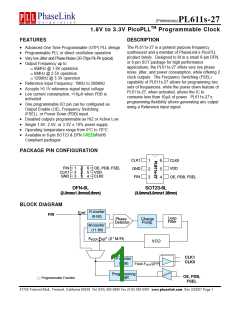
1.8V to 3.3V PicoPLLTM Programmable Clock
FUNCTIONAL DESCRIPTION
PL611s-27 is a highly featured, very flexible, advanced programmable PLL design for high performance, low-
power, small form-factor applications. The PL611s-27 accepts a reference clock input of 1MHz to 200MHz and is
capable of producing two outputs up to 55MHz. This flexible design allows the PL611s-27 to deliver any PLL
generated frequency, FREF (Ref Clk) frequency or FREF /(2*P) to CLK0 and/or CLK1. Some of the design features
of the PL611s-27 are mentioned below:
PLL Programming
Output Enable (OE)
The PLL in the PL611s-27 is fully programmable.
The PLL is equipped with an 8-bit input frequency
divider (R-Counter), and an 11-bit VCO frequency
feedback loop divider (M-Counter). The output of
the PLL is transferred to a 5-bit post VCO divider (P-
Counter). The output frequency is determined by
the following formula [FOUT = FREF * M / (R * P) ].
The Output Enable feature allows the user to enable
and disable the clock output(s) by toggling the OE
pin. The OE pin incorporates a 60kΩ pull up
resistor giving a default condition of logic “1”.
The OE feature can be programmed to allow the
output to float (Hi Z), or to operate in the ‘Active low’
mode.
Clock Output (CLK0)
Power-Down Control (PDB)
CLK0 is the main clock output. The output of CLK0
can be configured as the PLL output (FVCO/(2*P)),
The Power Down (PDB) feature allows the user to
put the PL611s-27 into “Sleep Mode”. When
F
REF (Ref Clk Frequency) output, or FREF/(2*P)
activated (logic ‘0’), PDB ‘Disables the PLL, the
oscillator circuitry, counters, and all other active
circuitry. In Power Down mode the IC consumes
<10µA of power. The PDB pin incorporates a 60kΩ
pull up resistor giving a default condition of logic “1”.
output. The output drive level can be programmed to
Low Drive (4mA), Standard Drive (8mA) or High Drive
(16mA). The maximum output frequency is 125MHz.
Clock Output (CLK1)
The PDB feature can be programmed to allow the
output to float (Hi Z), or to operate in the ‘Active low’
mode.
The CLK1 feature allows the PL611s-27 to have an
additional clock output. This output can be
programmed to one of the following:
Frequency Select (FSEL)
F
F
REF - Reference (Ref Clk) Frequency
REF / 2
The Frequency Select (FSEL) feature allows the
PL611s-27 to switch between two pre-programmed
outputs allowing the device “On the Fly” frequency
switching. The FSEL pin incorporates a 60kΩ pull
up resistor giving a default condition of logic “1”.
CLK0
CLK0 / 2
When using the OE function CLK1 will remain
“Always On” and will not be disabled when OE is
pulled low. When using the PDB function CLK1 will
be disabled along with CLK0. The output drive level
can be programmed to Low Drive (4mA), Standard
Drive (8mA) or High Drive (16mA). The maximum
output frequency is 125MHz.
47745 Fremont Blvd., Fremont, California 94538 Tel (510) 492-0990 Fax (510) 492-0991 www.phaselink.com Rev 2/25/07 Page 3

 PLL [ PHASELINK CORPORATION ]