Philips Semiconductors
Preliminary specification
Economy audio CODEC for MiniDisc (MD)
home stereo and portable applications
UDA1341TS
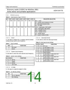
• DATA0
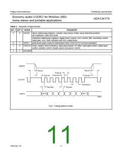
7.21 Programming the sound processing and other
features
There are two addressing modes: direct addressing
mode and extended addressing mode.
The sound processing and other feature values are stored
in independent registers.
Direct addressing mode is using the 2 MSB bits of the
data byte. Via this addressing mode the features
volume, bass boost, treble, peak position, de-emphasis,
mute, and mode can be controlled directly.
The first selection of the registers is achieved by the choice
of data type that is transferred. This is performed in the
address mode using bit 0 and bit 1 (see Table 4).
The second selection is performed by the 2 or 3 MSBs of
the data byte (bits 7 and 6 or bits 7, 6 and 5).
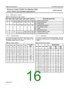
Extended addressing mode is provided for controlling
the features digital mixer, AGC control, MIC sensitivity,
input gain, AGC time constants, and AGC output level.
An extended address can be set via the EA registers
(3 bits). The data in the extended registers can be set by
writing data to the ED registers (5 bits).
The other bits in the data byte (bits 5 to 0 or bits 4 to 0)
represent the value that is placed in the selected registers.
For the UDA1341TS the following modes can be selected:
• STATUS
• DATA1
In this mode the features reset, system clock frequency,
data input format, DC-filter, input gain switch, output
gain switch, polarity control, double speed and power
control can be controlled.
In this mode the detected peak level value can be read
out.
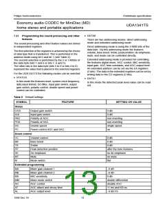
Table 5 Default settings
SYMBOL
Status
FEATURE
SETTING OR VALUE
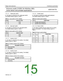
OGS
IGS
PAD
PDA
DS
Output gain switch
Input gain switch
Polarity of ADC
Polarity of DAC
Double speed
0 dB
0 dB
non-inverting
non-inverting
single speed
on
PC
Power control ADC and DAC
Direct control
VC
BB
TR
PP
DE
MT
M
Volume control
0 dB
Bass boost
Treble
0 dB
0 dB
Peak detection position
De-emphasis
Mute
after the tone features
no de-emphasis
no mute
Mode switch
flat
Extended programming
MA
MB
MS
MM
AG
AT
Mixer gain channel 1
−6 dB
Mixer gain channel 2
MIC sensitivity
−6 dB
0 dB
Mixer mode switch
AGC control
double differential
disable AGC
11 ms and100 ns
−9 dB FS
AGC attack and decay time
AGC output level
AL
1998 Dec 18
13

 NXP [ NXP ]