Philips Semiconductors
Product specification
High speed CAN transceiver
TJA1041A
HIGH
LOW
handbook, full pagewidth
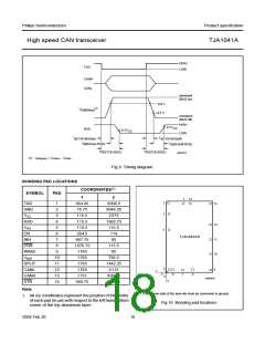
TXD
CANH
CANL
dominant
(BUS on)
0.9 V
0.5 V
(1)
V
i(dif)(bus)
recessive
(BUS off)
HIGH
0.7V
CC
RXD
0.3V
CC
LOW
t
t
d(TXD-BUSon)
d(TXD-BUSoff)
t
t
d(BUSon-RXD)
d(BUSoff-RXD)
t
t
PD TXD-RXD
(
)
(
)
PD TXD-RXD
MGS377
(1) Vi(dif)(bus) = VCANH − VCANL
.
Fig.9 Timing diagram.
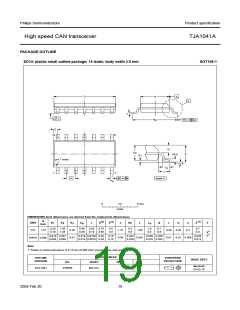
BONDING PAD LOCATIONS
COORDINATES(1)
SYMBOL
PAD
x
y
1
14
handbook, halfpage
2
3
13
12
TXD
GND
VCC
1
2
664.25
75.75
115.5
115.5
115.5
264.5
667.75
1076.75
1765
3004.5
3044.25
2573
3
RXD
VI/O
4
1862.75
115.5
114
5
4
EN
6
TJA1041AU
11
10
INH
7
85
ERR
WAKE
VBAT
SPLIT
CANL
CANH
STB
8
115.5
85
9
10
11
12
13
14
1765
792.5
1442.25
2115
1765
5
1765
9
x
0
6
7
8
1751
3002.5
3004.5
0
MDB634
y
940.75
Note
The reverse side of the bare die must be connected to ground.
1. All x/y coordinates represent the position of the centre
of each pad (in µm) with respect to the left hand bottom
corner of the top aluminium layer.
Fig.10 Bonding pad locations.
2004 Feb 20
18

 NXP [ NXP ]