Philips Semiconductors
Product specification
New In Car Entertainment car radio tuner IC with
Precision Adjacent Channel Suppression (NICE-PACS)
TEA6848H
12 I2C-BUS PROTOCOL
12.1.2 I2C-BUS PULL-UP RESISTORS
12.1 I2C-bus specification
When the IC is used together with the TEA688x or
TEF689x and both SCL and SDA lines are connected via
the I2C-bus to the TEA688x or TEF689x, the pull-up
resistors of the tuner IC should be connected to the digital
supply voltage of the TEA688x or TEF689x. Otherwise an
I2C-bus pull-down can occur switching off the tuner IC
supply when the I2C-bus buffer interface of the TEA688x
or TEF689x is enabled for data transfer to the tuner IC.
Information about the I2C-bus can be found in the brochure
“The I2C-bus and how to use it” (order number
9398 393 40011).
The standard I2C-bus specification is expanded by the
following definitions.
IC addresses:
• 1st IC address C2H: 1100001 R/W
• 2nd IC address C0H: 1100000 R/W.
12.1.3 FREQUENCY SETTING
For new frequency setting, in both AM and FM mode, the
programmable divider is enabled by setting bit MUTE = 1.
To select an FM frequency, two I2C-bus transmissions are
necessary:
Structure of the I2C-bus logic: slave transceiver with auto
increment.
Subaddresses are not used.
• First: bit MUTE = 1
A second I2C-bus address can be selected by connecting
pin FREF via a 68 kΩ resistor to GND.
• Second: bit MUTE = 0.
12.1.4 DEFAULT SETTINGS
12.1.1 DATA TRANSFER
No default settings at power-on reset. One I2C-bus
transmission is required to program the IC.
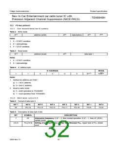
Data sequence: address, byte 0, byte 1, byte 2, byte 3,
byte 4, byte 5, byte 6, and byte 7. The data transfer has to
be in this order. The LSB = 0 indicates a WRITE operation
to the TEA6848H.
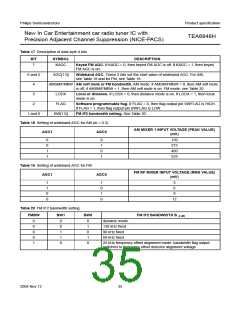
12.1.5 TIMING REQUIREMENTS
Table 1 Timing requirements of I2C-bus software
Bit 7 of each byte is considered the MSB and has to be
transferred as the first bit of the byte.
FUNCTION
TIMING
Switching from 400 ms (10 µF at pin CAGC)
FM to AM
The data becomes valid at the output of the internal
latches with the acknowledge of each byte. A STOP
condition after any byte can shorten transmission times.
Switching from 100 ms (10 µF at pin CAGC; wideband
AM to FM
position has to be set for at least
100 ms to activate speed-up circuitry)
When writing to the transceiver by using the STOP
condition before completion of the whole transfer:
Start-up in FM wideband position has to be set for at
• The remaining bytes will contain the old information
mode
least 100 ms to activate speed-up
circuitry
• If the transfer of a byte is not completed, this byte is lost
and the previous information is available.
Switching to
500 µs (18 nF at pin TACD; wideband
dynamic mode position has to be set for at least
500 µs to activate clamping circuitry at
pin TACD)
2004 Nov 12
31

 NXP [ NXP ]