Philips Semiconductors
Product specification
New In Car Entertainment (NICE) car radio
TEA6845AH; TEA6845H
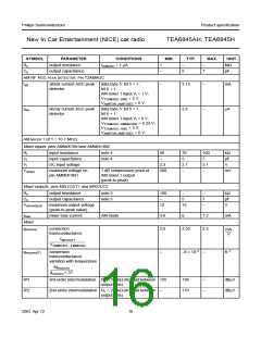
SYMBOL
Ro
Co
PARAMETER
CONDITIONS
IIAMAGC = 1 µA
MIN.
TYP.
MAX.
UNIT
output resistance
1
−
−
MΩ
output capacitance
−
5
7
pF
AM RF AGC PEAK DETECTOR: PIN T2AMAGC
Iatt
attack current AGC peak
detector
data byte 5: bit 5 = 1,
bit 6 = 1;
AM mixer 1 input Vi = 1 V;
VT2AMAGC−GND = 3 V;
VAMIF2IN−AMIF2DEC = 0 V
−
−
3.15
2.6
−
−
mA
Idec
decay current AGC peak
detector
data byte 5: bit 5 = 1,
bit 6 = 1;
µA
AM mixer 1 input Vi = 0 V;
VT2AMAGC−AMMIN1IN2 = 0.25 V;
VT2AMAGC−GND = 3 V;
VAMIF2IN−AMIF2DEC = 0 V
AM MIXER 1 (IF1 = 10.7 MHZ)
Mixer inputs: pins AMMIX1IN1and AMMIX1IN2
Ri
input resistance
input capacitance
DC input voltage
note 4
note 4
50
70
5
100
7
kΩ
pF
V
Ci
−
VI
2.3
2.7
−
3.1
−
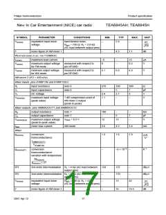
Vi(max)
maximum voltage on
pin AMMIX1IN1
1 dB compression point of
AM mixer 1 output
(peak-to-peak)
500
mV
Mixer outputs: pins MIX1OUT1 and MIXOUT2
Ro
output resistance
note 5
note 5
100
−
−
−
7
−
kΩ
pF
V
Co
output capacitance
5
Vo(max)(p-p)
maximum output voltage
(peak-to-peak value)
12
15
Ibias
mixer bias current
AM mode
4.8
2.0
6
7.2
3.2
mA
Mixer
gm(conv)
conversion
transconductance
2.55
mA
--------
V
IMIXOUT1
---------------------------------------------------
VFMMIXIN1 – FMMIXIN2
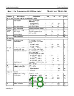
gm(conv)(T)
conversion
−
−9 × 10⁻⁴
−
K−1
transconductance
variation with temperature
∆gm(conv)
--------------------------------
g
m(conv) × ∆T
IP3
IP2
3rd-order intermodulation RL = 2.8 kΩ (AC load between 135
138
170
−
−
dBµV
dBµV
output pins)
2nd-order intermodulation RL = 2.8 kΩ (AC load between
−
output pins)
2001 Apr 12
16

 NXP [ NXP ]