Philips Semiconductors
Product specification
Self Tuned Radio (STR)
TEA5757; TEA5759
Description of the bus
Table 2 Bus-clock functions
The TEA5757; TEA5759 radio has a bus which consists of
three wires, as shown in Table 1.
BUS-CLOCK
LOW
MO/ST (PIN 24)
RESULT
stereo
LOW
HIGH
LOW
HIGH
LOW
HIGH
HIGH
mono
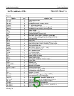
Table 1 Bus signals
tuned
SIGNAL
DESCRIPTION
PIN
not tuned
BUS-CLOCK
DATA
software driven clock input
data input/output
27
28
29
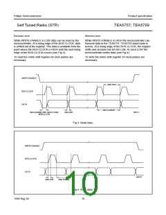
The TEA5757; TEA5759 has a 25-bit shift register;
see Table 3 for an explanation of the shift register bits.
WRITE-ENABLE write/read input
If in search mode no transmitter can be found, all
frequency bits of the shift register are set to logic 0.
These three signals, together with the mono/stereo pin
(MO/ST; pin 24), communicate with the microcontroller.
The mono/stereo indicator has two functions, which are
controlled by the BUS-CLOCK, as shown in Table 2.
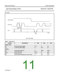
The bus protocol is depicted in Figs 3 and 4.
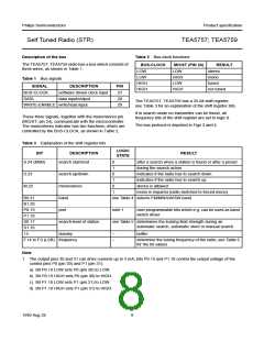
Table 3 Explanation of the shift register bits
LOGIC
STATE
BIT
DESCRIPTION
search start/end
RESULT
S.24 (MSB)
0
1
0
1
0
1
after a search when a station is found or after a preset
during the search action
D.23
M.22
search up/down
mono/stereo
band
indicates if the radio has to search down
indicates if the radio has to search up
stereo is allowed
mono is required (radio switched to forced mono)
B0.21
B1.20
P0.19
P1.18
S0.17
S1.16
15
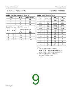
see Table 4 selects FM/MW/LW/SW band
port
note 1
user programmable bits which e.g. can be used as band
switch driver
search-level of station
dummy
see Table 5 determines the locking field strength during an
automatic search, automatic store or manual search
−
−
buffer
F.14 to F.0 (LSB) frequency
determine the tuning frequency of the radio; see Table 6
for the bit values
Note
1. The output pins 30 and 31 can drive currents up to 5 mA; bits P0.19 and P1.18 control the output voltage of the
control pins P0 (pin 30) and P1 (pin 31):
a) Bit P0.19 LOW sets P0 (pin 30) to LOW.
b) Bit P0.19 HIGH sets P0 (pin 30) to HIGH.
c) Bit P1.18 LOW sets P1 (pin 31) to LOW.
d) Bit P1.18 HIGH sets P1 (pin 31) to HIGH.
1999 Aug 26
8

 NXP [ NXP ]