Philips Semiconductors
Product specification
Self Tuned Radio (STR)
TEA5757; TEA5759
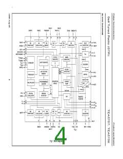
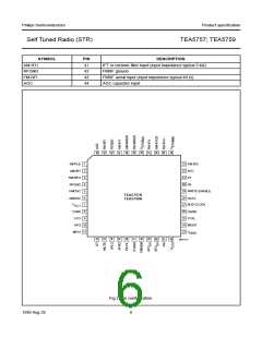
PINNING
SYMBOL
PIN
DESCRIPTION
RIPPLE
AM-RFI
1
ripple capacitor input
AMRF input
2
FM-RFO
RFGND
FMOSC
AMOSC
VCC1
3
parallel tuned FMRF circuit to ground
RF ground and substrate
4
5
parallel tuned FM-oscillator circuit to ground
parallel tuned AM-oscillator circuit to ground
supply voltage
6
7
TUNE
8
tuning current output
VCO
9
voltage controlled oscillator input
AM/FM AF output (output impedance typical 5 kΩ)
stereo decoder input (input impedance typical 150 kΩ)
loop-filter input
AFO
10
11
12
13
14
15
16
17
18
19
20
21
22
23
24
25
26
27
28
29
30
31
32
33
34
35
36
37
38
39
40
MPXI
LFI
MUTE
mute input
AFLO
left channel output (output impedance typical 4.3 kΩ)
right channel output (output impedance typical 4.3 kΩ)
pilot detector filter input
AFRO
PILFIL
IFGND
FMDEM
AFC(n)
AFC(p)
FSI
ground of IF, detector and MPX stage
ceramic discriminator input
AFC negative output
AFC positive output
field-strength indicator
VCC2
supply voltage for tuning
VDDD
digital supply voltage
MO/ST
XTAL
mono/stereo and tuning indication output
crystal input
DGND
BUS-CLOCK
DATA
digital ground
bus-clock input
bus data input/output
WRITE-ENABLE
P0
bus write-enable input
programmable output port (P0)
programmable output port (P1)
450 kHz LC-circuit
P1
AFC
FM-IFI2
VSTAB(B)
FM-IFO1
AM-IFI/O2
FM-IFI1
VSTAB(A)
FM-MIXER
AM-MIXER
FMIF input 2 (input impedance typical 330 Ω)
internal stabilized supply voltage (B)
FMIF output 1 (output impedance typical 330 Ω)
input/output to IF-Tank (IFT); output: current source
FMIF input 1 (input impedance typical 330 Ω)
internal stabilized supply voltage (A)
ceramic filter output (output impedance typical 330 Ω)
open-collector output to IFT
1999 Aug 26
5

 NXP [ NXP ]