TDA8922B
Philips Semiconductors
2 × 50 W class-D power amplifier
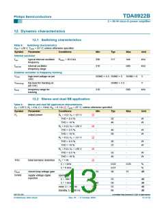
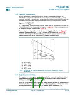
12. Dynamic characteristics
12.1 Switching characteristics
Table 8:
Switching characteristics
VDD = ±26 V; Tamb = 25 °C; unless otherwise specified.
Symbol
Parameter
Conditions
Min
Typ
Max
Unit
Internal oscillator
fosc
typical internal oscillator
frequency
ROSC = 30.0 kΩ
290
210
317
-
344
600
kHz
kHz
fosc(int)
internal oscillator
frequency range
External oscillator or frequency tracking
VOSC
high-level voltage on pin
OSC
SGND + 4.5 SGND + 5
SGND + 6
600
V
VOSC(trip)
ftrack
trip level for tracking on
pin OSC
-
SGND + 2.5 -
V
frequency range for
tracking
210
-
kHz
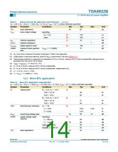
12.2 Stereo and dual SE application
Table 9:
Stereo and dual SE application characteristics
VP = ±26 V; RL = 6 Ω; fi = 1 kHz; RsL < 0.1 Ω [1]; Tamb = 25 °C; unless otherwise specified.
Symbol
Parameter
Conditions
Min
Typ
Max
Unit
[2]
[2]
[2]
[2]
[3]
Po
output power
RL = 4 Ω; VP = ±21 V
THD = 0.5 %
THD = 10 %
-
-
32
40
-
-
W
W
RL = 6 Ω; VP = ±26 V
THD = 0.5 %
THD = 10 %
-
-
40
50
-
-
W
W
RL = 8 Ω; VP = ±21 V
THD = 0.5 %
THD = 10 %
-
-
20
25
-
-
W
W
RL = 8 Ω; VP = ±26 V
THD = 0.5 %
THD = 10 %
-
-
32
40
-
-
W
W
THD
total harmonic distortion
closed loop voltage gain
Po = 1 W
fi = 1 kHz
-
0.02
0.07
30
0.05
-
%
fi = 6 kHz
-
%
Gv(cl)
29
31
dB
[4]
SVRR
supply voltage ripple
rejection
operating
fi = 100 Hz
-
55
50
55
80
-
-
-
-
dB
dB
dB
dB
fi = 1 kHz
40
-
[4]
[4]
mute; fi = 100 Hz
standby; fi = 100 Hz
-
9397 750 13357
© Koninklijke Philips Electronics N.V. 2004. All rights reserved.
Preliminary data sheet
Rev. 01 — 1 October 2004
13 of 32

 NXP [ NXP ]