Philips Semiconductors
Product specification
I2C-bus autosync deflection controller for
PC monitors
TDA4856
X-ray protection
Table 2 Calculation of ffr(V) total spread
Contributing elements
The X-ray protection input XRAY (pin 2) provides a voltage
detector with a precise threshold. If the input voltage at
XRAY exceeds this threshold for a certain time, then
control bit SOFTST is reset, which switches the IC into
protection mode. In this mode several pins are forced into
defined states:
Minimum frequency offset between ffr(V) and 10%
lowest trigger frequency
Spread of IC
Spread of RVREF
Spread of CVCAP
Total
±3%
±1%
±5%
19%
HUNLOCK (pin 17) is floating
The capacitor connected to HPLL2 (pin 30) is
discharged
Horizontal output stage (HDRV) is floating
B+ control driver stage (BDRV) is floating
CLBL provides a continuous blanking signal.
Result for 50 to 160 Hz application:
50 Hz
ffr(V)
=
= 42 Hz
---------------
1.19
The AGC of the vertical oscillator can be disabled by
setting control bit AGCDIS via the I2C-bus. A precise
external current has to be injected into VCAP (pin 24) to
obtain the correct vertical size. This special application
mode can be used when the vertical sync pulses are
serrated (shifted); this condition is found in some display
modes, e.g. when using a 100 Hz up converter for video
signals.
There are two different methods of restarting ways the IC:
1. XSEL (pin 9) is open-circuit or connected to ground.
The control bit SOFTST must be set to logic 1 via the
I2C-bus. Then the IC returns to normal operation via
soft start.
2. XSEL (pin 9) is connected to VCC via an external
resistor. The supply voltage of the IC must be switched
off for a certain period of time, before the IC can be
restarted again using the standard power-on
procedure.
Application hint: VAGC (pin 22) has a high input
impedance during scan. Therefore, the pin must not be
loaded externally otherwise non-linearities in the vertical
output currents may occur due to the changing charge
current during scan.
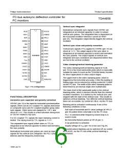
Vertical oscillator and amplitude control
This stage is designed for fast stabilization of vertical size
after changes in sync frequency conditions.
Adjustment of vertical size, VGA overscan and EHT
compensation
The free-running frequency ffr(V) is determined by the
resistor RVREF connected to pin 23 and the capacitor
CVCAP connected to pin 24. The value of RVREF is not only
optimized for noise and linearity performance in the whole
vertical and EW section, but also influences several
internal references. Therefore the value of RVREF must not
be changed. Capacitor CVCAP should be used to select the
free-running frequency of the vertical oscillator in
accordance with the following formula:
There are four different ways to adjust the amplitude of the
differential output currents at VOUT1 and VOUT2.
1. Register VGAIN changes the vertical size without
affecting any other output signal of the IC. This
adjustment is meant for factory alignments.
2. Register VSIZE changes not only the vertical size, but
also provides the correct tracking of all other related
waveforms (see Section “Tracking of vertical
adjustments”). This register should be used for user
adjustments.
1
ffr(V)
=
-----------------------------------------------------------
10.8 × RVREF × CVCAP
To achieve a stabilized amplitude the free-running
frequency ffr(V), without adjustment, should be at least 10%
lower than the minimum trigger frequency.
3. For the VGA350 mode register VOVSCN can activate
a +17% step in vertical size.
4. VSMOD (pin 21) can be used for a DC controlled EHT
compensation of vertical size by correcting the
The contributions shown in Table 2 can be assumed.
differential output currents at VOUT1 and VOUT2.
The EW waveforms, vertical focus, pin unbalance and
parallelogram corrections are not affected by VSMOD.
1999 Jul 13
9

 NXP [ NXP ]