Philips Semiconductors
Product specification
2 to 6 W audio power amplifier
TDA1011
Ripple rejection (note 6)
f = 1 to 10 kHz
RR
RR
typ.
>
42 dB
35 dB
35 mA
f = 100 Hz; C2 = 1 µF
Bootstrap current at onset of clipping; pin 4 (r.m.s. value)
I
typ.
4(rms)
Notes
1. Measured with an ideal coupling capacitor to the speaker load.
2. Measured with a load resistor of 20 kΩ.
3. Measured at P = 1 W ; the frequency response is mainly determined by C1 and C3 for the low frequencies and by
o
C4 for the high frequencies.
4. Independent of load impedance of preamplifier.
5. Unweighted r.m.s. noise voltage measured at a bandwidth of 60 Hz to 15 kHz (12 dB/octave).
6. Ripple rejection measured with a source impedance between 0 and 2 kΩ (maximum ripple amplitude: 2 V).
7. The tab must be electrically floating or connected to the substrate (pin 9).
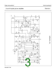
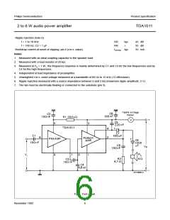
Fig.3 Test circuit.
November 1982
6

 NXP [ NXP ]