Philips Semiconductors
Product specification
Universal LCD driver for low multiplex
rates
PCF8576
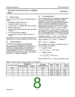
6.4
LCD drive mode waveforms
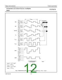
6.4.3
1 : 3 MULTIPLEX DRIVE MODE
When three backplanes are provided in the LCD, the 1 : 3
multiplex drive mode applies, as shown in Fig.7.
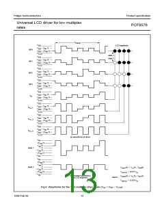
6.4.1
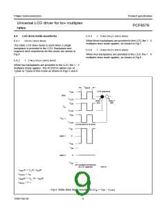
STATIC DRIVE MODE
The static LCD drive mode is used when a single
backplane is provided in the LCD. Backplane and
segment drive waveforms for this mode are shown in
Fig.4.
6.4.4
1 : 4 MULTIPLEX DRIVE MODE
When four backplanes are provided in the LCD, the 1 : 4
multiplex drive mode applies, as shown in Fig.8.
6.4.2
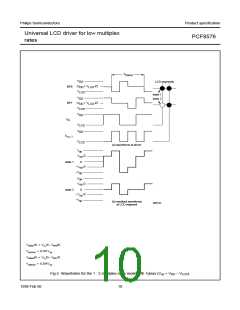
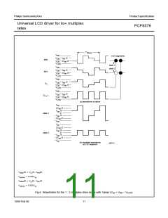
1 : 2 MULTIPLEX DRIVE MODE
When two backplanes are provided in the LCD, the 1 : 2
multiplex mode applies. The PCF8576 allows use of
1⁄2bias or 1⁄3bias in this mode as shown in Figs 5 and 6.
T
frame
LCD segments
V
DD
BP0
V
LCD
state 1
(on)
state 2
(off)
V
DD
S
n
V
LCD
V
DD
S
n
1
V
LCD
(a) waveforms at driver
V
op
0
state 1
V
op
V
op
state 2
0
V
op
(b) resultant waveforms
at LCD segment
MBE539
Vstate1(t) = VS (t) – VBP0(t)
n
Von(rms) = Vop
Vstate2(t) = VS (t) – VBP0(t)
n + 1
Voff(rms) = 0 V
Fig.4 Static drive mode waveforms (Vop = VDD − VLCD).
1998 Feb 06
9

 NXP [ NXP ]