Philips Semiconductors
Product specification
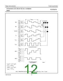
Universal LCD driver for low multiplex
rates
PCF8576
6.3
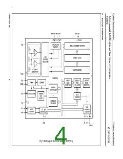
LCD voltage selector
6.1
Power-on reset
The LCD voltage selector co-ordinates the multiplexing of
the LCD in accordance with the selected LCD drive
configuration. The operation of the voltage selector is
controlled by MODE SET commands from the command
decoder. The biasing configurations that apply to the
preferred modes of operation, together with the biasing
characteristics as functions of Vop = VDD − VLCD and the
resulting discrimination ratios (D), are given in Table 2.
At power-on the PCF8576 resets to a starting condition as
follows:
1. All backplane outputs are set to VDD
2. All segment outputs are set to VDD
.
.
3. The drive mode ‘1 : 4 multiplex with 1⁄3bias’ is selected.
4. Blinking is switched off.
5. Input and output bank selectors are reset (as defined
in Table 5).
6. The I2C-bus interface is initialized.
A practical value for Vop is determined by equating Voff(rms)
with a defined LCD threshold voltage (Vth), typically when
the LCD exhibits approximately 10% contrast. In the static
drive mode a suitable choice is Vop > 3Vth approximately.
7. The data pointer and the subaddress counter are
cleared.
Multiplex drive ratios of 1 : 3 and 1 : 4 with 1⁄2bias are
Data transfers on the I2C-bus should be avoided for 1 ms
following power-on to allow completion of the reset action.
possible but the discrimination and hence the contrast
ratios are smaller ( 3 = 1.732 for 1 : 3 multiplex or
21
6.2
The full-scale LCD voltage (Vop) is obtained from
DD − VLCD. The LCD voltage may be temperature
LCD bias generator
= 1.528 for 1 : 4 multiplex).
----------
3
The advantage of these modes is a reduction of the LCD
full-scale voltage Vop as follows:
V
compensated externally through the VLCD supply to pin 12.
Fractional LCD biasing voltages are obtained from an
internal voltage divider of the three series resistors
connected between VDD and VLCD. The centre resistor can
be switched out of the circuit to provide a 1⁄2bias voltage
level for the 1 : 2 multiplex configuration.
• 1 : 3 multiplex (1⁄2bias):
Vop
=
6 × Voff rms = 2.449 Voff(rms)
• 1 : 4 multiplex (1⁄2bias):
(4 × 3)
-----------------------
3
Vop
=
= 2.309 Voff(rms)
These compare with Vop = 3 Voff(rms) when 1⁄3bias is used.
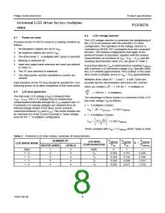
Table 2 Preferred LCD drive modes: summary of characteristics
NUMBER OF
V on(rms)
Voff(rms) V on(rms)
-------------------- --------------------
LCD BIAS
CONFIGURATION
D =
--------------------
Voff(rms)
LCD DRIVE MODE
Vop
Vop
BACKPLANES
LEVELS
static
1 : 2
1 : 2
1 : 3
1 : 4
1
2
2
3
4
2
3
4
4
4
static
0
1
∞
1
⁄
2
0.354
0.333
0.333
0.333
0.791
0.745
0.638
0.577
2.236
2.236
1.915
1.732
1
⁄
3
1
⁄
3
1
⁄
3
1998 Feb 06
8

 NXP [ NXP ]