Philips Semiconductors
Product specification
Remote 16-bit I/O expander for I2C-bus
PCF8575
CHARACTERISTICS OF THE I2C-BUS
6.4
Acknowledge
6
The I2C-bus is for bidirectional, 2-line communication
between different ICs or modules. The two lines are a
serial data line (SDA) and a serial clock line (SCL). Both
lines must be connected to a positive supply via a pull-up
resistor when connected to the output stages of a device.
Data transfer may be initiated only when the bus is not
busy.
The number of data bytes transferred between the START
and the STOP conditions from transmitter to receiver is not
limited. Each byte of eight bits is followed by one
acknowledge bit. The transmitter must release the SDA
line before the receiver can send an acknowledge bit.
A slave receiver which is addressed must generate an
acknowledge after the reception of each byte. Also a
master must generate an acknowledge after the reception
of each byte that has been clocked out of the slave
transmitter. The device that acknowledges has to pull
down the SDA line during the acknowledge clock pulse, so
that the SDA line is stable LOW during the HIGH period of
the acknowledge related clock pulse, set-up and hold
times must be taken into account.
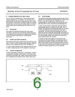
6.1
Bit transfer
One data bit is transferred during each clock pulse.
The data on the SDA line must remain stable during the
HIGH period of the clock pulse as changes in the data line
at this time will be interpreted as control signals
(see Fig.3).
A master receiver must signal an end of data to the
transmitter by not generating an acknowledge after the
last byte that has been clocked out of the slave. This is
done by the master receiver by holding the SDA line HIGH.
In this event the transmitter must release the data line to
enable the master to generate a STOP condition.
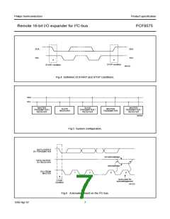
6.2
START and STOP conditions
Both data and clock lines remain HIGH when the bus is not
busy. A HIGH-to-LOW transition of the data line, while the
clock is HIGH is defined as the START condition (S).
A LOW-to-HIGH transition of the data line while the clock
is HIGH is defined as the STOP condition P (see Fig.4).
6.3
System configuration
A device generating a message is a ‘transmitter’, a device
receiving the message is the ‘receiver’. The device that
controls the message is the ‘master’ and the devices which
are controlled by the master are the ‘slaves’ (see Fig.5).
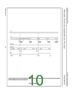
handbook, full pagewidth
SDA
SCL
data line
stable;
data valid
change
of data
allowed
MBC621
Fig.3 Bit transfer.
1999 Apr 07
6

 NXP [ NXP ]