Philips Semiconductors
Product specification
High performance low power mixer FM IF system
SA615
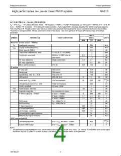
AC ELECTRICAL CHARACTERISTICS
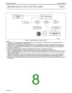
T = 25°C; V = +6V, unless otherwise stated. RF frequency = 45MHz + 14.5dBV RF input step–up; IF frequency = 455kHz; R17 = 5.1k; RF
A
CC
level = –45dBm; FM modulation = 1kHz with +8kHz peak deviation. Audio output with C-message weighted filter and de-emphasis capacitor.
Test circuit Figure 3. The parameters listed below are tested using automatic test equipment to assure consistent electrical characterristics.
The limits do not represent the ultimate performance limits of the device. Use of an optimized RF layout will improve many of the listed
parameters.
LIMITS
SYMBOL
PARAMETER
TEST CONDITIONS
SA615
TYP
UNITS
MIN
MAX
Mixer/Osc section (ext LO = 300mV)
f
Input signal frequency
500
150
5.0
MHz
MHz
dB
IN
f
Crystal oscillator frequency
Noise figure at 45MHz
OSC
Third-order input intercept point
Conversion power gain
f1 = 45.00; f2 = 45.06MHz
Matched 14.5dBV step-up
50Ω source
-12
13
dBm
dB
8.0
3.0
-1.7
4.7
dB
RF input resistance
RF input capacitance
Mixer output resistance
Single-ended input
kΩ
3.5
4.0
pF
(Pin 20)
1.25
1.50
kΩ
IF section
IF amp gain
Limiter gain
50Ω source
39.7
62.5
-109
33
dB
dB
50Ω source
Input limiting -3dB, R = 5.1k
Test at Pin 18
80% AM 1kHz
dBm
dB
17
AM rejection
25
60
43
mV
RM
Audio level, R = 100k
15nF de-emphasis
150
260
10
S
Unmuted audio level, R = 100k
150pF de-emphasis
RF level -118dB
530
12
mV
dB
dB
dB
mV
V
11
SINAD sensitivity
THD
S/N
Total harmonic distortion
-30
-42
68
Signal-to-noise ratio
No modulation for noise
IF level = -118dBm
IF level = -68dBm
1
IF RSSI output, R = 100kΩ
0
160
2.5
4.8
80
800
3.3
5.8
9
1.7
3.6
IF level = -18dBm
V
RSSI range
R = 100kΩ Pin 16
9
dB
dB
kΩ
kΩ
kΩ
kΩ
kΩ
RSSI accuracy
R = 100kΩ Pin 16
9
+2
IF input impedance
1.40
0.85
1.40
1.6
1.0
1.6
58
IF output impedance
Limiter intput impedance
Unmuted audio output resistance
Muted audio output resistance
58
RF/IF section (int LO)
Unmuted audio level
System RSSI output
mV
S
RM
4.5V = V , RF level = -27dBm
450
4.3
CC
4.5V = V , RF level = -27dBm
V
CC
NOTE:
1. The generator source impedance is 50Ω, but the SA615 input impedance at Pin 18 is 1500Ω. As a result, IF level refers to the actual signal
that enters the SA615 input (Pin 8) which is about 21dB less than the ”available power” at the generator.
4
1997 Nov 07

 NXP [ NXP ]