Philips Semiconductors
Product specification
Temperature monitor for microprocessor systems
NE1617
FEATURES
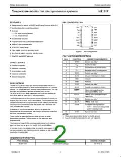
PIN CONFIGURATION
• Replacement for Maxim MAX1617 and Analog Devices ADM1021
• Monitors local and remote temperature
• Accuracy
– ± 2°C local (on-chip) sensor
– ± 3°C remote sensor
TEST
1
2
3
4
5
6
7
8
16 TEST
V
15 STBY
14 SCLK
13 TEST
12 SDATA
11 ALERT
10 ADD0
DD
D+
D–
TEST
ADD1
GND
GND
• No calibration required
• Programmable over/under temperature alarm
• SMBus 2-wire serial interface
9
TEST
• 3V to 5.5V supply range
SL01202
• 70µa supply current in operating mode
• 3µa (typical) supply current in standby mode
• Small 16–lead QSOP package
Figure 1. Pin configuration
PIN FUNCTION DESCRIPTION
PIN #
FUNCTION
DESCRIPTION/COMMENTS
1
1
2
TEST
Factory use only
APPLICATIONS
• Desktop computers
• Notebook computers
• Smart battery packs
• Industrial controllers
• Telecom equipment
2
V
DD
Positive supply
3
D+
D–
Positive side of remote sensor
Negative side of remote sensor
4
1
5
TEST
ADD1
GND
GND
TEST
ADD0
ALERT
Factory use only
6
Device address pin (3-State)
7
Ground
Ground
8
DESCRIPTION
1
9
Factory use only
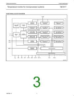
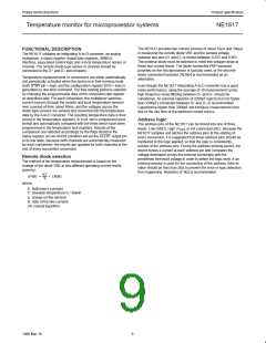
The NE1617 is an accurate two-channel temperature monitor. It
measures the temperature of itself and the temperature of a remote
sensor. The remote sensor is a diode connected transistor. This can
be in the form of either a discrete NPN/PNP, such as the
2N3904/2N3906, or a diode connected PNP built into another die,
such as is done on some INTEL microprocessors.
10
11
Device address pin (3-State)
Open drain output used as
interrupt or SMBus alert
12
SDATA
SMBus serial data input/output
open drain
The temperature of both the remote and local sensors is stored in a
register that can be read via a 2-wire SMBus. The temperatures are
updated at a rate that is programmable via the SMBus (the average
supply current is dependent upon the update rate—the faster the
rate, the higher the current).
1
13
14
15
TEST
SCLK
STBY
Factory use only
SMBus clock input
Hardware standby input pin
HIGH = normal operating mode
LOW = standby mode
In addition to the normal operation, which is to update the
temperature at the programmed rate, there is a one shot mode that
will force a temperature update.
1
16
TEST
Factory use only
NOTES:
1. These pins should either float or be tied to ground.
There is also an alarm that senses either an over or under
temperature condition. The trip points for this alarm are also
programmable.
2. V pin should be decoupled by a 0.1µF capacitor.
DD
The device can have 1 of 9 addresses (determined by 2 address
pins), so there can be up to 9 of the NE1617 on the SMBus.
It can also be put in a standby mode (in order to save power). This
can be done either with software (over the SMBus) or with hardware
(using the STANDBY pin).
ORDERING INFORMATION
PART NUMBER
PACKAGE
16-lead QSOP package
DRAWING NUMBER
SOT519–1
NE1617DS
2
1999 Mar 19
853–2144 21065

 NXP [ NXP ]