KMA220
NXP Semiconductors
Dual channel programmable angle sensor
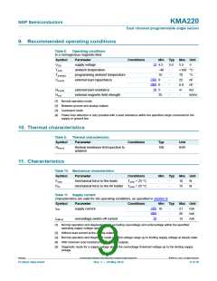
9. Recommended operating conditions
Table 8.
Operating conditions
In a homogenous magnetic field.
Symbol
VDD
Parameter
Conditions
Min Typ Max Unit
[1]
supply voltage
4.5
40
10
0
5.0
5.5
V
Tamb
ambient temperature
programming ambient temperature
external load capacitance
-
-
-
-
-
-
+160 C
Tamb(pr)
CL(ext)
70
22
6.8
-
C
[1][2]
[2][3]
[4]
nF
0
nF
RL(ext)
Hext
external load resistance
5
k
external magnetic field strength
35
kA/m
[1] Normal operation mode.
[2] Between ground and analog outputs.
[3] Command mode.
[4] Power-loss detection is only possible with a load resistance within the specified range connected to the
supply or ground line.
10. Thermal characteristics
Table 9.
Thermal characteristics
Symbol
Parameter
Conditions
Typ
Unit
Rth(j-a)
thermal resistance from junction to
ambient
100
K/W
11. Characteristics
Table 10. Mechanical characteristics
Symbol
Flead
Parameter
Conditions
Min Typ Max Unit
mechanical force to the leads
Tamb = 25 C
-
-
-
-
10
15
N
N
Ffin
mechanical force to the fin holder Tamb = 25 C
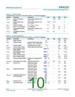
Table 11. Supply current
Characteristics are valid for the operating conditions, as specified in Section 9.
Symbol
Parameter
Conditions
Min Typ Max Unit
[1][2]
[3][4]
[5]
IDD
supply current
10
-
-
-
-
21
26
12
mA
mA
mA
Ioff(ov)
overvoltage switch-off current
-
[1] Normal operation and diagnostic mode excluding overvoltage and undervoltage within the specified
operating supply voltage range.
[2] Without load current at the analog output.
[3] Normal operation and diagnostic mode over full voltage range up to limiting supply voltage at steady state.
[4] With minimum load resistance at the analog outputs.
[5] Diagnostic mode for a supply voltage above the overvoltage threshold voltage up to the limiting supply
voltage.
KMA220
All information provided in this document is subject to legal disclaimers.
© NXP B.V. 2012. All rights reserved.
Product data sheet
Rev. 1 — 24 May 2012
9 of 36

 NXP [ NXP ]