KMA220
NXP Semiconductors
Dual channel programmable angle sensor
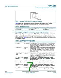
Table 6 describes the diagnostic behavior and the resulting output voltage depending on
the error case. Furthermore the duration and termination condition to enter and leave the
diagnostic mode are given, respectively.
Table 6.
Diagnostic behavior
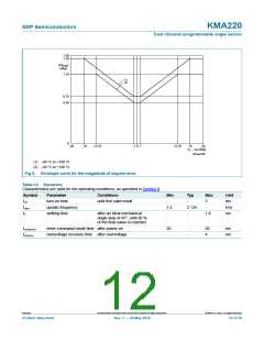
Diagnostic condition Duration
Analog output
Termination condition
Low voltage
Overvoltage
1 s < t < 10 s
4 %VDD
functional or normal
operation
1 s < t < 10 s
4 %VDD
functional or normal
operation
[2]
[2]
[2]
[2]
Checksum error
Double-bit error
Magnet-loss
n/a
n/a
4 %VDD or 96 %VDD
4 %VDD or 96 %VDD
power-on reset[1]
power-on reset[1]
magnet present[1]
power-on reset
0.5 ms < t < 6 ms 4 %VDD or 96 %VDD
2 ms 4 %VDD or 96 %VDD
Power-loss
[1] Status bit stays set in command register until power-on reset.
[2] Depending on the diagnostic level setting.
8. Limiting values
Table 7.
Limiting values
In accordance with the Absolute Maximum Rating System (IEC 60134).
Symbol
VDD
Parameter
Conditions
Min
Max
+16
+16
16
Unit
V
supply voltage
0.3
0.3
Vth(ov)
VO
output voltage
V
[1]
VO(ov)
overvoltage output voltage
Tamb < 140 C
V
at t < 1 h
Ir
reverse current
Tamb < 70 C
-
150
+160
70
mA
C
C
C
Tamb
Tamb(pr)
Tstg
ambient temperature
programming ambient temperature
storage temperature
40
10
40
+125
Non-volatile memory
tret(D)
data retention time
Tamb = 50 C
17
-
-
year
Nendu(W_ER) write or erase endurance
Tamb(pr) = 70 C
100
cycle
[1] Overvoltage on analog output and supply within the specified operating voltage range.
KMA220
All information provided in this document is subject to legal disclaimers.
© NXP B.V. 2012. All rights reserved.
Product data sheet
Rev. 1 — 24 May 2012
8 of 36

 NXP [ NXP ]