ISP1160
Embedded USB Host Controller
Philips Semiconductors
Bit
7
6
5
reserved
N/A
4
3
2
1
DR[2:0]
IS
0
Symbol
Reset
Access
N/A
R
N/A
R
N/A
R
N/A
R
IS
IS
R
R/W
R/W
R/W
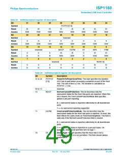
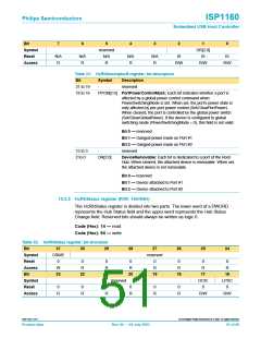
Table 31: HcRhDescriptorB register: bit description
Bit
Symbol
Description
31 to 19
18 to 16
-
reserved
PPCM[2:0] PortPowerControlMask: Each bit indicates whether a port is
affected by a global power control command when
PowerSwitchingMode is set. When set, the port’s power state is
only affected by per-port power control (Set/ClearPortPower).
When cleared, the port is controlled by the global power switch
(Set/ClearGlobalPower). If the device is configured to global
switching mode (PowerSwitchingMode = 0), this field is not valid.
Bit 0 — reserved
Bit 1 — Ganged-power mask on Port #1
Bit 2 — Ganged-power mask on Port #2
15 to 3
2 to 0
-
reserved
DR[2:0]
DeviceRemovable: Each bit is dedicated to a port of the Root
Hub. When cleared, the attached device is removable. When set,
the attached device is not removable.
Bit 0 — reserved
Bit 1 — Device attached to Port #1
Bit 2 — Device attached to Port #2
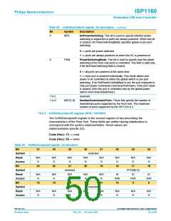
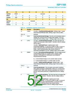
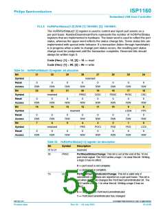
10.3.3 HcRhStatus register (R/W: 14H/94H)
The HcRhStatus register is divided into two parts. The lower word of a DWORD
represents the Hub Status field and the upper word represents the Hub Status
Change field. Reserved bits should always be written as logic 0.
Code (Hex): 14 — read
Code (Hex): 94 — write
Table 32: HcRhStatus register: bit allocation
Bit
31
CRWE
0
30
29
28
27
26
25
24
Symbol
Reset
Access
Bit
reserved
0
R
0
R
0
R
0
R
0
R
0
R
0
R
W
23
22
21
20
19
18
17
16
Symbol
Reset
Access
reserved
OCIC
0
LPSC
0
0
0
0
0
0
0
R
R
R
R
R
R
R/W
R/W
9397 750 11371
© Koninklijke Philips Electronics N.V. 2003. All rights reserved.
Product data
Rev. 04 — 04 July 2003
51 of 88

 NXP [ NXP ]