Philips Semiconductors
Product specification
Triacs
BT137X series
IGT(Tj)
IGT(25 C)
BT137
typ
IT / A
25
20
15
10
5
BT137
Tj = 125 C
Tj = 25 C
3
T2+ G+
T2+ G-
T2- G-
T2- G+
max
2.5
2
Vo = 1.264 V
Rs = 0.0378 Ohms
1.5
1
0.5
0
0
0
0.5
1
1.5
VT / V
2
2.5
3
-50
0
50
100
150
Tj / C
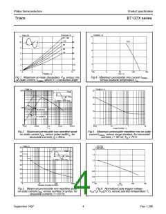
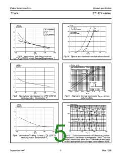
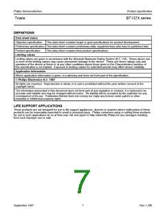
Fig.7. Normalised gate trigger current
IGT(Tj)/ IGT(25˚C), versus junction temperature Tj.
Fig.10. Typical and maximum on-state characteristic.
IL(Tj)
IL(25 C)
BT137
Zth j-hs (K/W)
10
1
TRIAC
with heatsink compound
3
2.5
2
without heatsink compound
unidirectional
bidirectional
1.5
1
t
P
D
0.1
0.01
p
t
0.5
0
10us
0.1ms
1ms
10ms
tp / s
0.1s
1s
10s
-50
0
50
Tj / C
100
150
Fig.8. Normalised latching current IL(Tj)/ IL(25˚C),
versus junction temperature Tj.
Fig.11. Transient thermal impedance Zth j-hs, versus
pulse width tp.
dV/dt (V/us)
1000
IH(Tj)
IH(25C)
TRIAC
3
2.5
2
off-state dV/dt limit
BT137...G SERIES
BT137 SERIES
100
BT137...F SERIES
1.5
1
dIcom/dt =
10 A/ms
7.9
6.1 4.7 3.6 2.8
10
0.5
0
1
-50
0
50
Tj / C
100
150
0
50
100
150
Tj / C
Fig.9. Normalised holding current IH(Tj)/ IH(25˚C),
versus junction temperature Tj.
Fig.12. Typical commutation dV/dt versus junction
temperature, parameter commutation dIT/dt. The triac
should commutate when the dV/dt is below the value
on the appropriate curve for pre-commutation dIT/dt.
September 1997
5
Rev 1.200

 NXP [ NXP ]