Philips Semiconductors
Product specification
Triacs
logic level
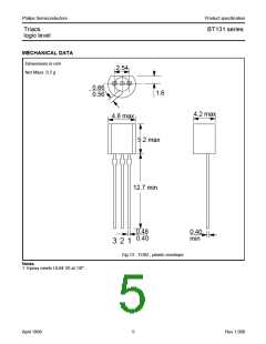
BT131 series
THERMAL RESISTANCES
SYMBOL PARAMETER
CONDITIONS
MIN. TYP. MAX. UNIT
Rth j-lead
Thermal resistance
junction to lead
Thermal resistance
junction to ambient
full cycle
-
-
-
-
-
60
80
-
K/W
K/W
K/W
half cycle
Rth j-a
pcb mounted;lead length = 4mm
150
STATIC CHARACTERISTICS
Tj = 25 ˚C unless otherwise stated
SYMBOL PARAMETER
CONDITIONS
MIN. TYP. MAX. UNIT
IGT
Gate trigger current
VD = 12 V; IT = 0.1 A
T2+ G+
-
-
-
-
0.4
1.3
1.4
3.8
3
3
3
7
mA
mA
mA
mA
T2+ G-
T2- G-
T2- G+
IL
Latching current
VD = 12 V; IGT = 0.1 A
T2+ G+
T2+ G-
T2- G-
T2- G+
-
1.2
4.0
1.0
2.5
1.3
1.2
0.7
0.3
0.1
5
8
mA
mA
mA
mA
mA
V
V
V
mA
-
-
5
-
8
IH
VT
VGT
Holding current
On-state voltage
Gate trigger voltage
VD = 12 V; IGT = 0.1 A
IT = 2.0 A
-
5
-
-
1.5
1.5
-
VD = 12 V; IT = 0.1 A
VD = 400 V; IT = 0.1 A; Tj = 125 ˚C
0.2
-
ID
Off-state leakage current VD = VDRM(max); Tj = 125 ˚C
0.5
DYNAMIC CHARACTERISTICS
Tj = 25 ˚C unless otherwise stated
SYMBOL PARAMETER
CONDITIONS
MIN. TYP. MAX. UNIT
dVD/dt
tgt
Critical rate of rise of
off-state voltage
Gate controlled turn-on
time
VDM = 67% VDRM(max); Tj = 125 ˚C;
exponential waveform; RGK = 1 kΩ
ITM = 1.5 A; VD = VDRM(max); IG = 0.1 A;
dIG/dt = 5 A/µs
5
-
15
2
-
-
V/µs
µs
April 1998
2
Rev 1.000

 NXP [ NXP ]