Philips Semiconductors
Product specification
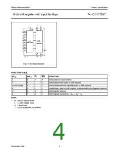
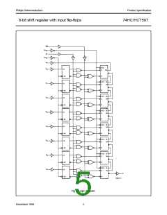
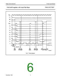
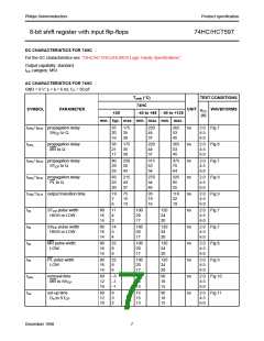
8-bit shift register with input flip-flops
74HC/HCT597
AC WAVEFORMS
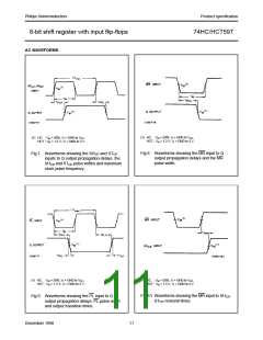
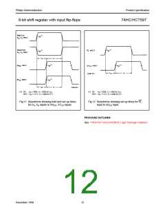
(1) HC : VM = 50%; VI = GND to VCC
.
(1) HC : VM = 50%; VI = GND to VCC
.
HCT : VM = 1.3 V; VI = GND to 3 V.
HCT : VM = 1.3 V; VI = GND to 3 V.
Fig.8 Waveforms showing the MR input to Q
output propagation delays and the MR
pulse width.
Fig.7 Waveforms showing the SHCP and STCP
inputs to Q output propagation delays, the
SHCP and STCP pulse widths and maximum
clock pulse frequency.
(1) HC : VM = 50%; VI = GND to VCC
.
(1) HC : VM = 50%; VI = GND to VCC.
HCT : VM = 1.3 V; VI = GND to 3 V.
HCT : VM = 1.3 V; VI = GND to 3 V.
Fig.10 Waveforms showing the MR input to SHCP
STCP removal times.
,
Fig.9 Waveforms showing the PL input to Q
output propagation delays, PL pulse width
and output transition times.
December 1990
11

 NXP [ NXP ]