Philips Semiconductors
Product specification
8-channel analog multiplexer/demultiplexer
74HC/HCT4051
AC CHARACTERISTICS FOR 74HCT
GND = 0 V; tr = tf = 6 ns; CL = 50 pF
Tamb (°C)
TEST CONDITIONS
OTHER
74HCT
SYMBOL PARAMETER
UNIT
VCC VEE
(V) (V)
+25
−40 to +85 −40 to +125
min. typ. max. min. max. min. max.
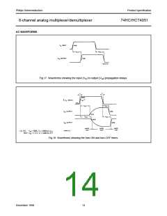
tPHL/ tPLH propagation
delay Vis to Vos
5
4
12
8
15
10
18
12
ns
ns
ns
ns
ns
4.5
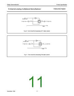
4.5 −4.5 (see Fig.17)
4.5 RL = 1 kΩ; CL = 50 pF
4.5 −4.5 (see Fig.18, 19 and 20)
4.5 RL = 1 kΩ; CL = 50 pF
4.5 −4.5 (see Fig.18, 19 and 20)
4.5 RL = 1 kΩ; CL = 50 pF
4.5 −4.5 (see Fig.18, 19 and 20)
4.5 RL = 1 kΩ; CL = 50 pF
4.5 −4.5 (see Fig.18, 19 and 20)
0
RL = ∞; CL = 50 pF
t
t
t
t
PZH/ tPZL turn “ON” time
E to Vos
26 55
16 39
69
49
83
59
0
PZH/ tPZL turn “ON” time
Sn to Vos
28 55
16 39
69
49
83
59
0
PHZ/ tPLZ turn “OFF”
time E to Vos
19 45
16 32
56
40
68
48
0
PHZ/ tPLZ turn “OFF”
time Sn to Vos
23 45
16 32
56
40
68
48
0
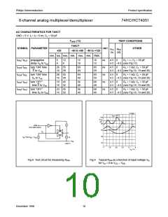
Fig.8 Test circuit for measuring RON
.
Fig.9 Typical RON as a function of input voltage Vis
for Vis = 0 to VCC − VEE
.
December 1990
10

 NXP [ NXP ]