Philips Semiconductors
Product specification
8-channel analog multiplexer/demultiplexer
74HC/HCT4051
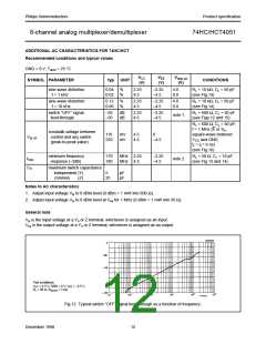
TEST CIRCUIT AND WAVEFORMS
Conditions
TEST
tPZH
tPZL
tPHZ
SWITCH
VEE
VCC
VEE
VCC
open
Vis
VCC
VEE
VCC
VEE
tr; tf
FAMILY AMPLITUDE
VM
fmax
;
OTHER
PULSE WIDTH
74HC
VCC
50%
1.3 V < 2 ns
< 2 ns
6 ns
6 ns
tPLZ
others
74HCT 3.0 V
pulse
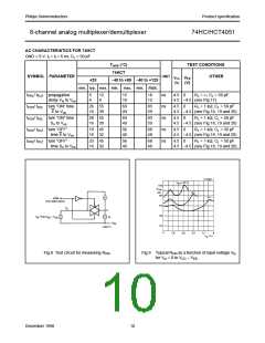
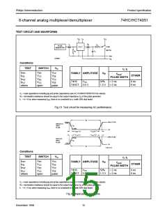
CL = load capacitance including jig and probe capacitance (see AC CHARACTERISTICS for values).
RT = termination resistance should be equal to the output impedance ZO of the pulse generator.
tr = tf = 6 ns; when measuring fmax, there is no constraint to tr, tf with 50% duty factor.
Fig.19 Test circuit for measuring AC performance.
Conditions
TEST
tPZH
tPZL
tPHZ
tPLZ
others
SWITCH
VEE
VCC
VEE
VCC
open
Vis
VCC
VEE
VCC
VEE
tr; tf
FAMILY AMPLITUDE
VM
fmax
;
OTHER
PULSE WIDTH
74HC
VCC
50%
1.3 V < 2 ns
< 2 ns
6 ns
6 ns
74HCT 3.0 V
pulse
CL = load capacitance including jig and probe capacitance (see AC CHARACTERISTICS for values).
RT = termination resistance should be equal to the output impedance ZO of the pulse generator.
tr = tf = 6 ns; when measuring fmax, there is no constraint to tr, tf with 50% duty factor.
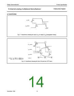
Fig.20 Input pulse definitions.
December 1990
15

 NXP [ NXP ]