Chip Resistor Networks
■ Construction (Example : EXBD)
Protective coating
Protective coating
Electrode
(Inner)
Alumina substrate
Electrode (Outer)
Electrode (Between)
Electrode (Inner)
Thick film
resistive element
Alumina substrate
Thick film
resistive element
■ Dimensions in mm (not to scale)
EXBD
EXBE
EXBA
EXBQ
0.33 0.15
0.5 0.2
0.2 0.1
+0.15
+0.1
–0.2
f0.2 0.1
0.2 0.1
0.7 0.2
0.15
f0.3
–0.05
0.2 0.1
0.3 0.2
+0.1
–0.2
0.3 0.2
0.3 0.1
f0.3
EXBA10P
*ꢁꢂ
*ꢁꢂ
*ꢁꢂ
ꢃꢄꢅ
0.5 0.1
0.8 0.1
0.635 0.10
0.55 0.10
1.27 0.10
6.4 0.2
0.55 0.10
0.25 0.10
4.0 0.2
3.20 0.15
0.3 0.1
0.25 0.10
0.55 0.10
0.45 0.10
0.4 0.2
3.8 0.2
0.5 0.2
0.35 0.20
EXBA10E
0.35 0.20
+0.20
0.15
–0.05
*ꢁꢂ
Mass (Weight)[1000 pcs.] : 10 g
Mass (Weight)[1000 pcs.] : 16 g
EXBA10P
Mass (Weight)[1000 pcs.] : 40 g
Mass (Weight)[1000 pcs.] : 9 g
■ Circuit Configuration
EXBD, EXBE
EXBA
EXBQ
EXBA10E
10
10
9
8
7
5
9
2
8
3
7
4
6
5
10
9
8
7
6
10
7
16 15 14 13 12 11
9
8
1
6
1
2
3
4
5
6
2
3
4
1
1
2
3
4
5
■ Ratings
Item
Specifications
Series
EXBD
EXBE
EXBA
EXBQ
Resistance Range
47 Ω to 1 MΩ (E12)
100 Ω to 470 kΩ (E6 series)
Resistance Tolerance
Number of Terminals
Number of Resistors
Power Rating at 70 °C
Limiting Element Voltage(1)
Maximum Overload Voltage(2)
T. C. R.
5ꢀ
10 terminals
8 element
16 terminals
15 element
0.025 W/element
25V
0.05 W/element
0.063 W/element
50 V
100 V
200 × 10–6/ °C
–55 °C to +125 °C
25V
50 V
50 V
Category Temperature Range
√
(1) Rated Continuous Working Voltage (RCWV) shall be determined from RCWV= Power Rating × Resistance Value, or Limiting Element Voltage
listed above, whichever less.
(2) Overload (Short-time Overload) Test Voltage (SOTV) shall be determined
from SOTV=2.5 × RCWV■ or Maximum Overload Voltage listed above whichever less.
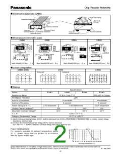
Power Derating Curve
–55 °C
70 °C
100
80
60
40
20
0
For resistors operated in ambient temperature above
70 °C, power rating shall be derated in accordance
with the figure on the right.
125 °C
20 40 60 80 100120140160180
Ambient Temperature (°C)
–60 –40 –20
0
Design and specifications are each subject to change without notice. Ask factory for the current technical specifications before purchase and/or use.
Should a safety concern arise regarding this product, please be sure to contact us immediately.
01 Aug. 2012
37

 PANASONIC [ PANASONIC ]