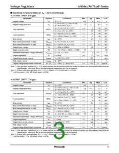
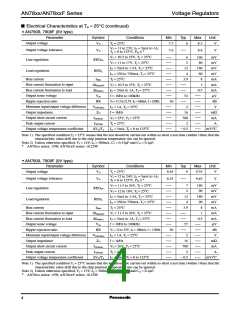
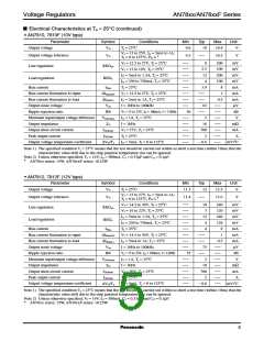
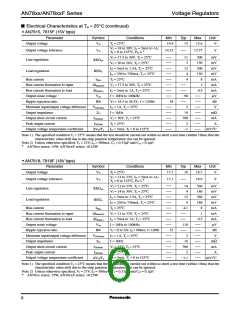
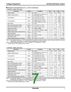
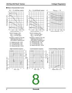
Voltage Regulators
AN78xx/AN78xxF Series
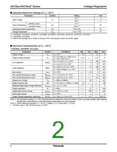
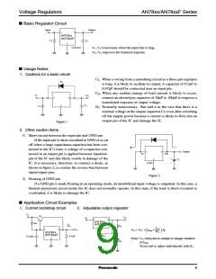
I Basic Regulator Circuit
Input
Output
1
3
AN78xx
AN78xxF
CI
CO
2
Common
CI : CI is necessary when the input line is long.
CO: CO improves the transient response.
I Usage Notes
1. Cautions for a basic circuit
CI: When a wiring from a smoothing circuit to a three-pin regulator
is long, it is likely to oscillate in output. A capacitor of 0.1µF to
0.47µF should be connected near an input pin.
Di
CO: When any sudden change of load current is likely to occur,
connect an electrolytic capacitor of 10µF to 100µF to improve a
transitional response of output voltage.
Di: Normally unnecessary. But add it in the case that there is a
residual voltage at the output capacitor Co even after switching
off the supply power because a current is likely to flow into an
output pin of the IC and damage the IC.
VI
VO
1
3
CO
2
CI
Figure 1
2. Other caution items
1) Short-circuit between the input pin and GND pin
If the input pin is short-circuitted to GND or is cut
off when a large capacitance capacitor has been con-
nected to the IC's load, a voltage of a capacitor con-
nected to an output pin is applied between input/out-
put of the IC and this likely results in damage of the
IC. It is necessary, therefore, to connect a diode, as
shown in figure 2, to counter the reverse bias between
input/output pins.
Output
1
3
In
Out
+
−
CO
2
GND
Figure 2
2) Floating of GND pin
If a GND pin is made floating in an operating mode, an unstabilized input voltage is outputted. In this case, a
thermal protection circuit inside the IC does not normally operate. In this state, if the load is short-circuited or
overloaded, it is likely to damage the IC.
I Application Circuit Examples
1. Current bootstrap circuit
2. Adjustable output regulator
VI
Q1
VO
VI
1
3
AN78xx
3Ω
IO
AN78xxF
R2
VO'
2
VO'
R2
1
3
VO
0.1µF
VO = VO' + IBias
+
R1
AN78xx
AN78xxF
IBias
0.33µF
2
Note) VO varies due to sample to sample variation
of IBias
Never fail to adjust individually with R1.
R1
.
9

 PANASONIC [ PANASONIC ]