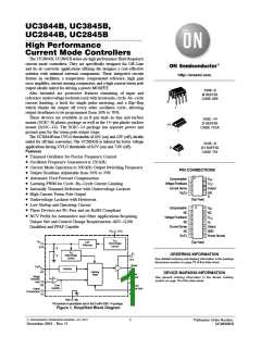
UC3844B, UC3845B, UC2844B, UC2845B
ELECTRICAL CHARACTERISTICS (V = 15 V [Note 11], R = 10 k, C = 3.3 nF. For typical values T = 25°C, for min/max
CC
T
T
A
values T is the operating ambient temperature range that applies [Note 12], unless otherwise noted.)
A
UC284xB
Typ
UC384xB, xBV, NCV384xBV
Characteristic
Symbol
Min
Max
Min
Typ
Max
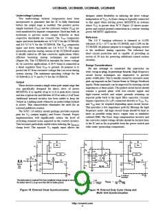
Unit
PWM SECTION
Duty Cycle
%
Maximum (UC284XB, UC384XB)
Maximum (UC384XBV)
Minimum
DC
47
−
−
48
−
−
50
−
0
47
46
−
48
48
−
50
50
0
(max)
DC
(min)
TOTAL DEVICE
Power Supply Current
I
mA
V
CC
Startup (V = 6.5 V for UCX845B,
−
0.3
0.5
−
0.3
0.5
CC
Startup (V = 14 V for UCX844B, BV)
CC
Operating (Note 11)
−
12
36
17
−
12
36
17
Power Supply Zener Voltage (I = 25 mA)
V
30
−
30
−
CC
Z
11. Adjust V above the Startup threshold before setting to 15 V.
CC
12.Low duty cycle pulse techniques are used during test to maintain junction temperature as close to ambient as possible.
T
= 0°C for UC3844B, UC3845B
= − 25°C for UC2844B, UC2845B
= − 40°C for UC384xBV, NCV384xBV
T
= + 70°C for UC3844B, UC3845B
= + 85°C for UC2844B, UC2845B
= +105°C for UC3844BV, UC3845BV
=+125°C for NCV384xBV
low
high
80
50
75
V
= 15 V
CC
3
1.ꢀC = 10 nF
T
2.ꢀC = 5.0 nF
T = 25°C
A
T
3.ꢀC = 2.0 nF
70
65
T
4.ꢀC = 1.0 nF
2
T
5.ꢀC = 500 pF
4
20
T
6.ꢀC = 200 pF
T
7.ꢀC = 100 pF
1
T
8.0
5.0
60
55
7
5
2.0
0.8
NOTE: Output switches at
1/2 the oscillator frequency
6
50
10 k
20 k
50 k
100 k
200 k
500 k
1.0 M
10 k
20 k
50 k 100 k
200 k
500 k 1.0 M
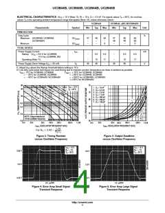
f , OSCILLATOR FREQUENCY (kHz)
OSC
f , OSCILLATOR FREQUENCY (kHz)
OSC
1.72
RTCT
For RT u 5 Kf X
Figure 2. Timing Resistor
versus Oscillator Frequency
Figure 3. Output Deadtime
versus Oscillator Frequency
V
CC
A = -1.0
T = 25°C
A
= 15 V
V
CC
A = -1.0
T = 25°C
A
= 15 V
V
V
2.55 V
3.0 V
2.5 V
2.5 V
2.0 V
2.45 V
0.5 ms/DIV
1.0 ms/DIV
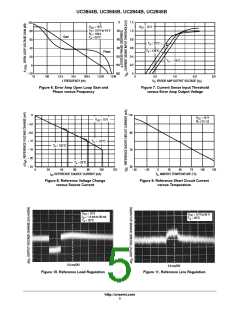
Figure 4. Error Amp Small Signal
Transient Response
Figure 5. Error Amp Large Signal
Transient Response
http://onsemi.com
4

 ONSEMI [ ONSEMI ]